
Luminance detector and detection method thereof

A technology of brightness detection and light to be measured, applied in the field of brightness measurement, brightness detector and its detection, to achieve the effect of small size of the instrument, accurate detection results and easy portability

Active Publication Date: 2015-01-21
无锡市星迪仪器有限公司
View PDF4 Cites 0 Cited by
  • Summary
  • Abstract
  • Description
  • Claims
  • Application Information

AI Technical Summary

Problems solved by technology

And it can also provide accurate detection results in non-specific detection environments

Method used


Image

  • Luminance detector and detection method thereof
  • Luminance detector and detection method thereof
  • Luminance detector and detection method thereof

Examples


Embodiment Construction

[0023] The present invention will be further described below in conjunction with specific drawings and embodiments.

[0024] Such as figure 1 , as shown in Figure 2:

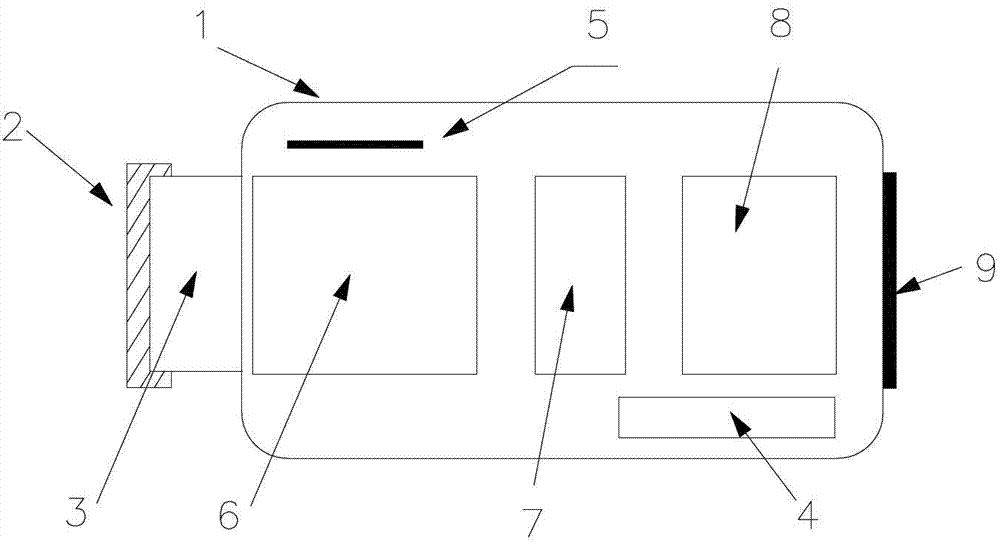
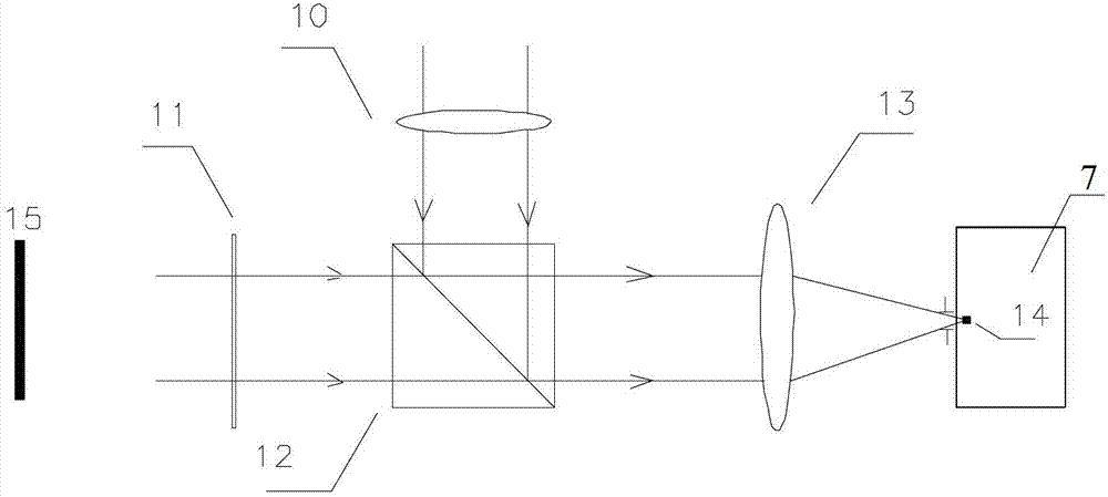
[0025] A brightness detector, comprising a housing 1, a constant temperature control unit 4 arranged in the housing 1, a standard light source 5, a light source acquisition unit 6, a photodetector 7, a processing unit 8, and a display arranged outside the housing 1 Unit 9; the light source collection unit 6 and the photodetector 7 are sequentially arranged along the optical path of the light to be measured sent by the tested light source 15; the light source collection unit 6 includes a beam splitting prism 12, which is arranged between the beam splitting prism 12 and the standard light source 5 The small objective lens 10 between them, the bandpass filter 11 arranged between the dichroic prism 12 and the light source 15 to be tested, and the imaging objective lens 13 arranged between the dichroic prism 12 and ...


PUM


Abstract

The invention provides a luminance detector, comprising a shell, a standard light source, a light source collecting unit, a photoelectric detector, a processing unit and a display unit, wherein the standard light source, the light source collecting unit, the photoelectric detector and the processing unit are arranged in the shell; the display unit is arranged outside the shell; the light source collecting unit and the photoelectric detector are arranged in sequence along the light path to be detected of a to-be-detected light source; and the light source collecting unit comprises a beam splitter prism, a small objective lens which is arranged between the beam splitting prism and the standard light source, a bandpass filter which is arranged between the beam splitting prism and the to-be-detected light source, and an imaging objective lens which is arranged between the beam splitting prism and the photoelectric detector. The luminance detector can be used for measuring the to-be-detected light source on the basis of a relative measurement theory, the usage range of the luminance detector can be effectively expanded, measurement can be carried out under a non-specified detection environment, and the influence of the noise and aging of the photoelectric detector on the luminance detection result is reduced. The luminance detector is small in size and light in weight.

Description

technical field [0001] The invention relates to a brightness detector and a detection method thereof, in particular to a brightness detector with a standard light source and a brightness measurement method using the brightness detector. Background technique [0002] Brightness is defined as the light intensity of a light source per unit area in a certain aspect, and brightness detectors are widely used in the field of brightness detection. At present, the commonly used brightness detectors generally work in the way of absolute measurement, that is, the photodetector responds to the detected light source and generates an electrical signal, and the system obtains the brightness of the detected light source according to the strength of the electrical signal. However, the traditional luminance detector has very high requirements on the environment, and usually can only work in a specific detection environment; at the same time, the noise of the photodetector itself and the aging...

Claims


Application Information

Patent Timeline
Patent Type & Authority Patents(China)
IPC IPC(8): G01J1/18
Inventor 谢卫陆飞蔡实
Owner 无锡市星迪仪器有限公司
Learn More