Pluggable planar optical waveguide device and manufacturing method thereof

A planar optical waveguide and pluggable technology, which is applied in the field of pluggable planar optical waveguide devices and its production, can solve the problems of many turnover links, difficulties in use and operation, and damage to optical fibers, so as to reduce production links and reduce Production cost, good stability effect

Active Publication Date: 2016-06-01
BROADEX TECH
View PDF6 Cites 0 Cited by
  • Summary
  • Abstract
  • Description
  • Claims
  • Application Information

AI Technical Summary

Problems solved by technology

The disadvantage of this structure is: the external size of the module box body 21 is large, and a single connector 23 takes up a lot of space, which cannot reflect the advantages of the small size of the planar optical waveguide device (in a typical 1x8 planar optical waveguide optical power splitter, that is, the packaging shell One end of 32 is an optical fiber 31, the other end is an 8-core ribbon optical fiber 33, and the size of the basic packaging shell 32 is 40 mm long, 4 mm wide, and 4 mm high), as attached image 3 shown
However, the disadvantage of this structure is that the product has bare optical fibers, and customers need to carefully manage the optical fibers during use, and the optical fibers are easily damaged during use and operation, which brings difficulties to use and operation.
Generally speaking, the production processes of these commonly used structures are lengthy and complicated, with many turnover links and high material consumption, and each has its own disadvantages when applied on the client side.

Method used


Image

  • Pluggable planar optical waveguide device and manufacturing method thereof
  • Pluggable planar optical waveguide device and manufacturing method thereof
  • Pluggable planar optical waveguide device and manufacturing method thereof

Examples


Embodiment 1

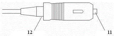
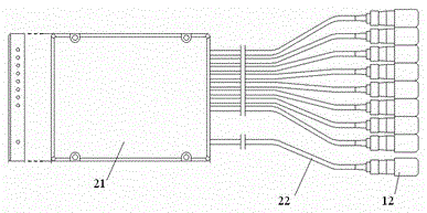
[0043] In this embodiment, the planar optical waveguide chip 100 adopts a planar optical waveguide splitter chip with single-channel input and eight-channel output, which has one input waveguide and eight output waveguides, and the two end faces are processed into 8 degrees; its input end is connected to The fiber optic assembly 300 uses Figure 10The single-channel fiber optic array 301 shown; its output is connected to Figure 11 An eight-lane connection ferrule 201 is shown.

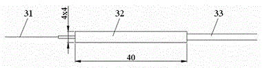
[0044] The single-channel optical fiber array 301 has an optical fiber, which is placed and fixed in the V-shaped groove of the optical fiber array with an adhesive, and the end face is processed to be 8 degrees to be precisely connected with the input waveguide of the planar optical waveguide optical power splitter chip; the other A certain length of optical fiber 400 can be reserved on the side according to application requirements, and a conventional single-channel connector can be added to the en...

Embodiment 2

[0049] In this embodiment, the overall structure of the pluggable planar optical waveguide device is similar to Embodiment 1, the only difference is that the optical fiber assembly uses a single-channel connection ferrule 302, such as Figure 14 shown.

[0050] One end face of the single-channel connection ferrule 302 is processed at 8 degrees, and its optical fiber is precisely connected to the waveguide; the other end face can be processed as a plane or an inclined plane, and has a guide pin 700 or a jack as a connector to ensure that the plugging application Precision alignment between the fibers in the splicing ferrule and the fibers in the customer end connector. The client's connector can be a regular single-channel connector.


PUM


Abstract

The invention relates to a pluggable planar optical waveguide device and a manufacturing method thereof. The pluggable planar optical waveguide device comprises a planar optical waveguide chip, an optical component and a connecting insertion core both connected with two ends of the chip respectively; the optical component and the connecting insertion core are internally provided with optical fibers corresponding to waveguides of the planar optical waveguide chip respectively, and the optical fibers are precisely butted with the waveguides one by one; and a connector is arranged on an end face outside the connecting insertion core. According to the invention, the size of the device is reduced, optical fibers exposed outside the device are reduced or prevented from being exposed outside the device, production links are reduced, the production cost is lowered, the assembly space for a customer is greatly saved, operations of the customer are facilitated, and operational and maintenance cost is lowered.

Description

technical field [0001] The invention relates to a planar optical waveguide device and a manufacturing method thereof, in particular to a pluggable planar optical waveguide device and a manufacturing method thereof. Background technique [0002] Due to the advantages of small size, high stability and reliability, and lower mass production costs, planar optical waveguide devices have increasingly replaced traditional micro-optical or other discrete devices, and play an increasingly important role in optical fiber communication systems and networks. more important role. [0003] Commercial planar optical waveguide devices usually use optical fiber as the medium for signal input and output, and are connected to links or devices by fusion splicing or connector splicing during application. The fusion splicing method requires an expensive optical fiber fusion splicing machine. Relatively speaking, the connector is cheap and easy to operate, and is welcomed by end users. attached ...

Claims


Application Information

Patent Timeline
Patent Type & Authority Patents(China)
IPC IPC(8): G02B6/38G02B6/255
Inventor 丁勇刘琳闫超朱伟
Owner BROADEX TECH
Why Eureka
Try Eureka