

Solar energy tracking device
A technology of solar tracking and hinged support, applied in the direction of using feedback control, etc., can solve the problems of slow rotation, large transmission ratio of the drive system, high cost and difficult to promote, and achieve the effect of cost realization and overload protection
- Summary
- Abstract
- Description
- Claims
- Application Information
AI Technical Summary
Problems solved by technology
Method used
Image

Examples
Embodiment Construction
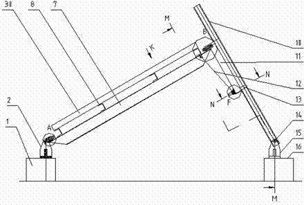
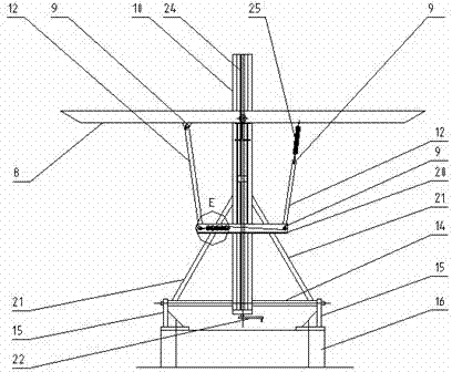
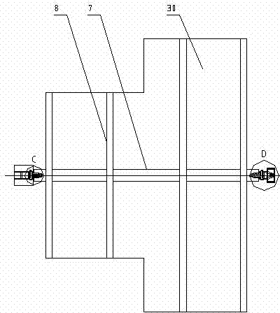
[0021] Referring to the accompanying drawings, a solar tracking device includes a foundation 1, a hinged support 2, a T-shaped shaft 3, a pin shaft 4, a shaft sleeve 5, a nut 6, a main beam 7, an auxiliary beam 8, a slide rail column 10, Ear plate 11, shaft 14, hinged support 2 15, foundation 2 16, diagonal brace 21, screw rod 24, screw nut 13, C-shaped slider 26, washer 27, cotter pin 28 and photovoltaic panel 30, sub-beam welding On the main girder, the photovoltaic panel is installed on the upper plane of the sub-girder, the two ends of the main girder are welded with bushings, and the bushing cooperates with the T-shaped shaft to form a sliding bearing. The two bushings are concentric, and their concentric axes are placed on a north-south vertical plane. Inside, is the axis for the east-west swing of the photovoltaic panel. There is a hole in the big end of the T-shaped shaft to fit with the pin shaft. The T-shaped shaft at the left lower end of the main beam is hinged to t...
PUM
 Abstract
Description
Claims
Application Information