Electromagnetic type power master switch

An electromagnetic, main switch technology, applied in electromagnetic relays, electromagnetic relay details, circuits, etc., can solve problems such as easy sintering of contact points, poor product on-off capability, magnetic loss, etc., to improve electromagnetic utilization and improve products quality, life extension effect

Inactive Publication Date: 2013-08-14
戴丁志
View PDF4 Cites 3 Cited by
  • Summary
  • Abstract
  • Description
  • Claims
  • Application Information

AI Technical Summary

Problems solved by technology

[0002] At present, the conventional main switch of the power supply uses a push rod (that is, a moving iron core) to drive the moving contact member to make the moving contact member and the fixed electrode connected or not to realize the switch control of the power supply. The radial direction of the push rod The activity is restricted but the axial movement is relatively free. Its own pull-in distance is only controlled by the self-weight of the push rod and the return spring, which makes the pull-in voltage of the product as a whole difficult to control and in an unstable state.
In addition, the main switch of the power supply is basically operated by the magnetic circuit between the coil and the shell. The structure of this magnetic circuit is loose and the distance is too far, resulting in a large amount of magnetic loss, so that the product can only use a return spring with a small force value ( and overtravel spring), resulting in the disadvantages of poor on-off capability of the product
Because the pull-in voltage of the main power switch product is unstable, and the pull-in voltage is not easy to adjust, resulting in the disadvantages of large magnetic loss and easy sintering of the contact points, and the failure of the main power switch applied to the car will bring unexpected hidden dangers to the car.

Method used


Image

  • Electromagnetic type power master switch

Examples


Embodiment Construction

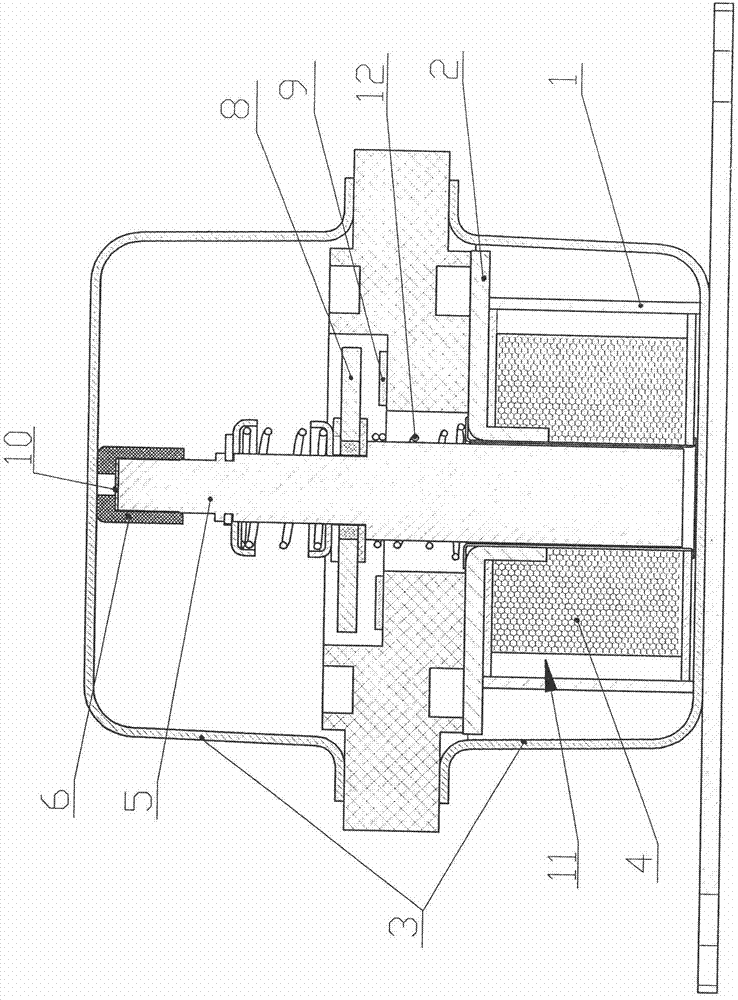
[0009] refer to figure 1 It can be seen that the electromagnetic power supply master switch of the present invention includes an electromagnetic component 11, a casing 3, a push rod 5 (ie, a moving iron core), a movable contact member 8, and a fixed electrode 9, and the upper top of the push rod 5 and the casing 3 Plastic cover 6 is housed between (upper). A gasket 10 is installed between the upper top of the push rod 5 and the plastic sleeve 6, and the fine adjustment of the suction distance of the product is realized by adding the gasket. Wherein, the return spring 12 is also housed on the push rod 5; the part of the push rod (that is, the moving iron core) has been improved, and the length of the entire moving iron core has been lengthened, so that the axial movement can be limited by the casing, Moreover, the internal suction distance can be adjusted through the plastic sleeve on the top of the moving iron core.

[0010] In order to reduce electromagnetic loss and improv...


PUM


Abstract

The invention discloses an electromagnetic type power master switch which comprises an electromagnetic component (11), an outer casing (3), a push rod (5), a movable contact piece (8) and a fixed electrode (9), wherein a plastic sleeve (6) is mounted between the upper top part of the push rod (5) and the outer casing (3); the outer casing is made of metal; the electromagnetic component (11) comprises an upper magnetic conductive plate (2) and a coil (4); and an inner iron ring (1) is mounted on the periphery of the coil and between the upper magnetic conductive plate and the lower part of the outer casing. According to the electromagnetic type power master switch, axial movement of the push rod is limited through the upper part of the outer casing, the pull-in distance inside a product is adjusted through the plastic sleeve, and accordingly, pull-in voltage becomes controllable and stable. The magnetic conductive plate, the inner iron core and the lower part of the outer casing wrap the coil wholly in a whole surrounding manner, so that the magnetic flux leakage quantity of the coil during working is reduced, the magnetic loss is smaller, the electromagnetic utilization ratio of the product is improved, the on-off capability of the product is enhanced, the product quality is improved on the whole, and the service life of the electromagnetic type power master switch is prolonged.

Description

technical field [0001] The invention relates to a contactor capable of turning on or cutting off a power supply, in particular to an electromagnetic power main switch. Background technique [0002] At present, the conventional main switch of the power supply uses a push rod (that is, a moving iron core) to drive the moving contact member to make the moving contact member and the fixed electrode connected or not to realize the switch control of the power supply. The radial direction of the push rod The movement is restricted but the axial movement is relatively free. Its own pull-in distance is only controlled by the self-weight of the push rod and the return spring, which makes the pull-in voltage of the product as a whole difficult to control and in an unstable state. In addition, the main switch of the power supply is basically operated by the magnetic circuit between the coil and the shell. The structure of this magnetic circuit is loose and the distance is too far, resul...

Claims


Application Information

Patent Timeline
Patent Type & Authority Applications(China)
IPC IPC(8): H01H50/16H01H50/18H01H50/02
Inventor 戴丁志孙作志戴猛仕
Owner 戴丁志
Why Eureka
Try Eureka