FC-AE-1553 based mixed avionics system tester

A technology of avionics system and tester, which is applied in the direction of transmission system, digital transmission system, electrical components, etc., and can solve the problems of avionics system testing that cannot mix multiple different protocols

Active Publication Date: 2013-08-14
HARBIN INST OF TECH
View PDF2 Cites 21 Cited by
  • Summary
  • Abstract
  • Description
  • Claims
  • Application Information

AI Technical Summary

Problems solved by technology

[0007] The purpose of the present invention is to solve the problem that it is currently impossible to test the avionics system that mixes multiple different protocols, thereby providing a hybrid avionics system tester based on FC-AE-1553

Method used


Image

  • FC-AE-1553 based mixed avionics system tester
  • FC-AE-1553 based mixed avionics system tester

Examples


specific Embodiment approach 1

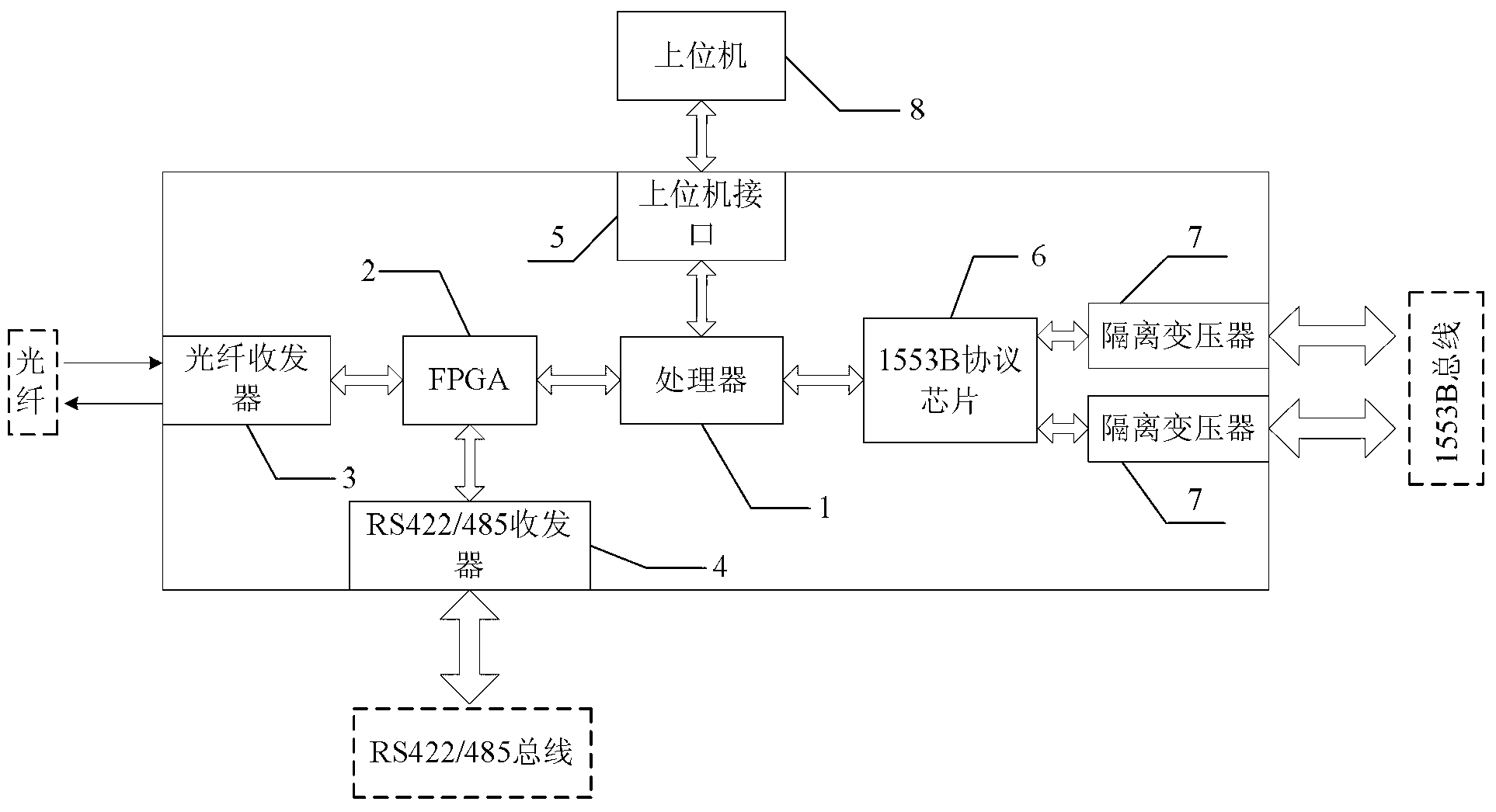
[0016] Specific implementation mode 1. Combination figure 1 Describe this specific implementation mode, based on FC-AE-1553 hybrid avionics system tester, it includes processor 1, FPGA2, optical fiber transceiver 3, RS422 / 485 transceiver 4, host computer interface circuit 5, 1553B protocol chip 6 , two isolation transformers 7 and a host computer 8;

[0017] The optical fiber transceiver 3 is used for mutual conversion of optical signals and electrical signals; the RS422 / 485 transceiver 4 is used for level conversion and data transmission and reception of RS-422 / 485 signals;

[0018] FPGA2 is used for data interaction with optical fiber transceiver 3; it is also used for data interaction with RS422 / 485 transceiver 4; it is also used for data interaction with processor 1;

[0019] The host computer signal input or output end of the processor 1 is connected to the signal output or input end of the host computer 8 through the host computer interface 5;

[0020] The 1553B protoc...

specific Embodiment approach 2

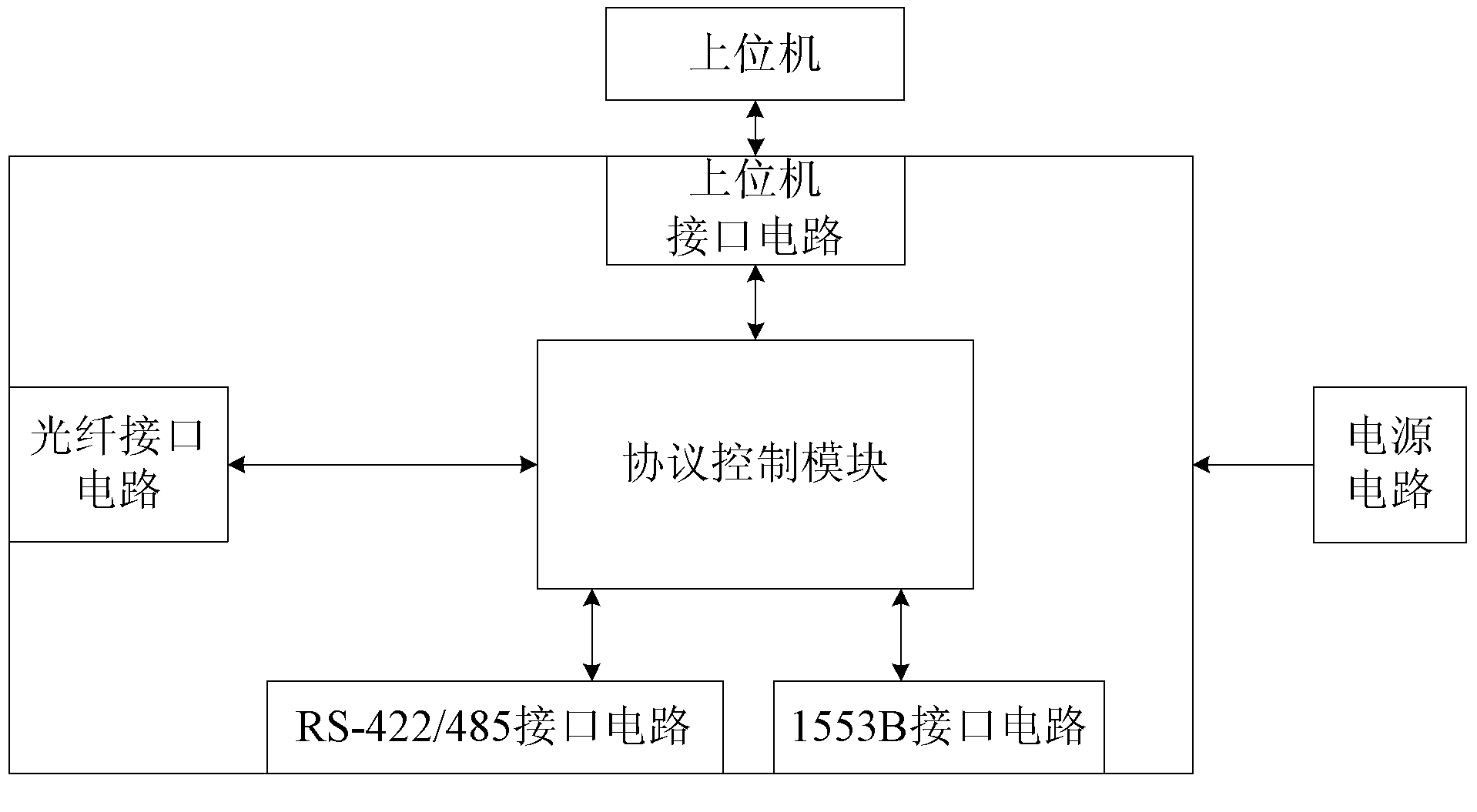
[0033] Embodiment 2. The difference between this embodiment and the hybrid avionics system tester based on FC-AE-1553 described in Embodiment 1 is that it also includes a power circuit, which is used to power the processor 1 , FPGA2, optical fiber transceiver 3, RS422 / 485 transceiver 4, host computer interface circuit 5, 1553B protocol chip 6 and two isolation transformers 7 provide working power.

specific Embodiment approach 3

[0034] Embodiment 3. The difference between this embodiment and the hybrid avionics system tester based on FC-AE-1553 described in Embodiment 1 is that the optical fiber transceiver 3 is realized by an SFP module whose model is FTLF8514P2, or by using a model Implemented for the SFP module of AFBR-57M5APZ.

[0035] The fiber optic interface is composed of two parts: fiber optic transceiver module and programmable logic device. When sending, the electrical signal is converted into an optical signal and sent into the optical fiber, and when receiving, the optical signal on the optical fiber is converted into an electrical signal for subsequent circuit use and processing. Among the fiber optic transceiver modules, the SFP module is the most widely used at present, which supports hot plugging, which is convenient for users to upgrade, maintain and replace it. You can choose FTLF8514P2 SFP module from Finisar Company, AFBR-57M5APZ from AVAGO Company and other SFP modules.


PUM


Abstract

An FC-AE-1553 based mixed avionics system tester relates to a mixed avionics system tester and aims to solve the problem that an avionics system mixing various different protocols can not be tested currently. The tester adopts the structure that a fiber transceiver is used for mutual conversion between optical signals and electrical signals; an RS422 / 485 transceiver is used for realizing level conversion and data transmit-receive of RS-422 / 485 signals; an FPGA (Field Programmable Gate Array) is used for performing data interaction with the fiber transceiver, the RS422 / 485 transceiver and the processor; a signal input or output end of an upper computer of the processor is connected with a signal output / input end of the upper computer; a 1553B protocol signal input or output end of the processor is connected with a 1553B protocol signal output or input end of a 1553B protocol chip; and the 1553B protocol chip is in data interaction with an external 1553B summary unit through two isolation transformators. The tester is suitable for testing of the mixed avionics system.

Description

technical field [0001] The invention relates to a hybrid avionics system tester. Background technique [0002] With the increasing requirements of avionics systems on data transmission speed, weight, anti-interference ability (electromagnetic compatibility) and channel capacity, Fiber Channel (FC) technology has gradually been applied to the design of new avionics systems. [0003] The Fiber Channel protocol is a high-speed serial communication protocol proposed by the American National Standards Institute (ANSI), which has the advantages of high bandwidth, high reliability, high transmission rate, and support for multiple upper-layer protocols. For the field of avionics, the FC-AE-1553 (Fibre Channel-Avionics Environment Upper Layer Protocol MIL-STD-1553) protocol based on the Fiber Channel protocol inherits and extends 1553B while maintaining all the advantages of the Fiber Channel protocol. The function of the bus can well meet the requirements of the avionics system in ...

Claims


Application Information

Patent Timeline
Patent Type & Authority Applications(China)
IPC IPC(8): H04L12/26H04L29/06
Inventor 乔家庆冯收付平凤雷张佳宁樊帆
Owner HARBIN INST OF TECH
Why Eureka
Try Eureka