Method for narrow-gap laser welding with filler wires for superconducting coil box

A welding method and technology of superconducting coils, applied in laser welding equipment, welding equipment, metal processing equipment, etc., can solve the problems of inability to meet the welding success rate, large heat-affected zone, and high cost of electron beam welding, and achieve extensive epitaxy. and extensible effects

Inactive Publication Date: 2013-08-21
SHENYANG SIASUN ROBOT & AUTOMATION
View PDF5 Cites 7 Cited by
  • Summary
  • Abstract
  • Description
  • Claims
  • Application Information

AI Technical Summary

Problems solved by technology

Based on the analysis of the above requirements, if the traditional arc welding is used, the heat-affected zone is large, the deformation after welding cannot meet the requirements, and the human influence factors are large, which cannot meet the requirements of the welding success rate, and the cost of electron beam welding is too high , the application value is low

Method used


Image

  • Method for narrow-gap laser welding with filler wires for superconducting coil box
  • Method for narrow-gap laser welding with filler wires for superconducting coil box
  • Method for narrow-gap laser welding with filler wires for superconducting coil box

Examples


Embodiment 1

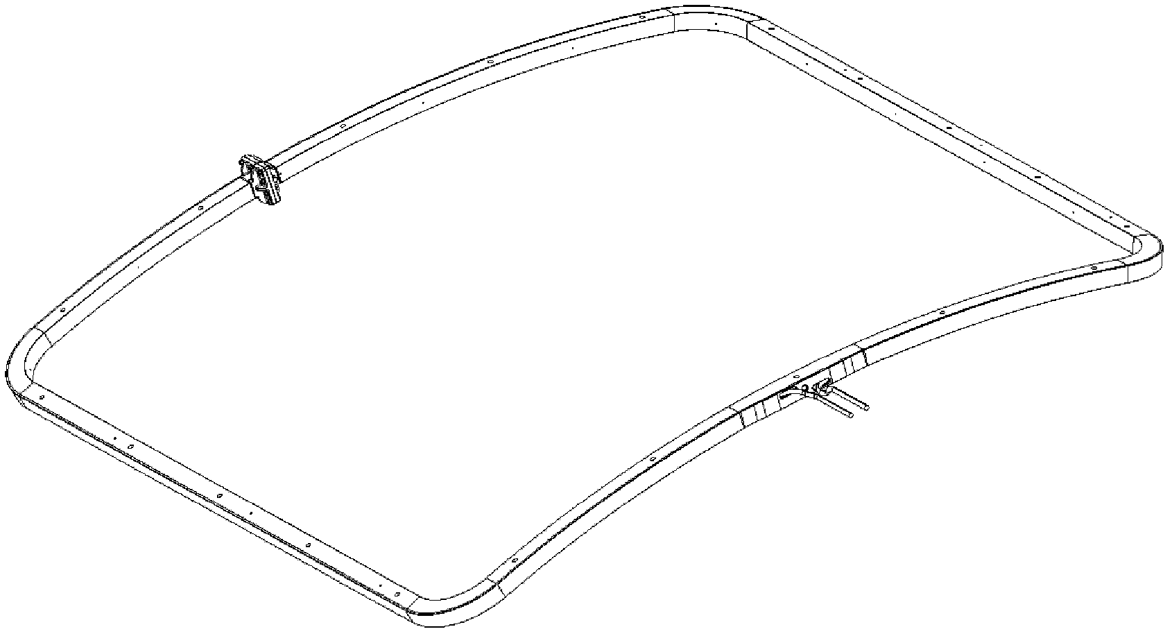
[0032] This embodiment is the implementation step of welding the coil box of the SCC structure. The structure of the coil box is as figure 1 As shown, the specific welding steps are:

[0033] (1) Process the welding seam of the superconducting coil box into a V-shaped groove and clean it with acetone to remove the oil and impurities on the surface.

[0034] (2) Fix the superconducting coil box to the load-bearing and profiling fixture, and use the fixture to tighten.

[0035] (3) The laser welding head and wire feed nozzle are connected with the robot arm to control the coordinated action of the robot and the laser.

[0036] (4) Start the welding device, set the laser output power, the distance between the processing head and the wire feeding nozzle and the surface of the workpiece, the shielding gas flow, the distance between the gas nozzle and the molten pool, the welding speed, the wire feeding speed, etc. to start welding.

[0037] (5) For the welding sequence of the SCC coil box, t...

Embodiment 2

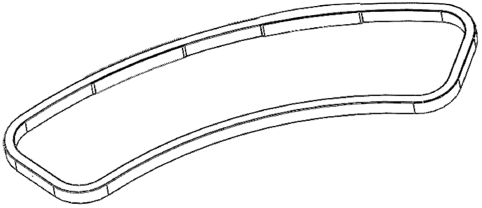
[0046] This embodiment is the implementation step of welding the coil box of the B / TCC structure. The structure of the coil box is as figure 2 As shown, the welding steps are roughly the same as those of Example 1, except that the B / TCC coil box is divided into a`, b` large arc segments, c`, d` straight line segments, e`, f, g`, h`small arc, such as Figure 4 As shown, the weld bead is divided into outer weld bead 3 and inner test weld bead 4, which are also symmetrical and alternately welded for each section and inner and outer weld beads. However, the coil box does not need to be turned over and the welding process is simplified. Therefore, in order to reduce heat Accumulation of input, using such as Figure 4 Welding sequence: Fill the first layer (A` layer) to the outer weld bead 3, then fill the first layer (B` layer) to the inner test bead 4, and then fill the second layer (C` layer) to the outer weld bead, Then fill in the D` layer, E` layer, F` layer in turn... and so o...


PUM

PropertyMeasurementUnit
sizeaaaaaaaaaa
thicknessaaaaaaaaaa

Abstract

The invention discloses a method for narrow-gap laser welding with filler wires for a superconducting coil box. The method is used for a superconducting coil box of a nuclear fusion reactor, and narrow-gap laser welding with filler wires is performed for a large superconducting coil shell by the aid of laser, so that the whole coil box is sealed. The method includes the steps: firstly, arranging a narrow-gap V-shaped groove on a part to be welded and cleaning weld joints and surfaces by the aid of acetone; secondly, fixedly placing the part to be welded on a bearing fixture and a profiling fixture and continuously welding truncated edges by tack welding and laser through a laser machining head driven by a robot; and finally, performing laser welding with multilayer hot filler wires for groove weld joints to integrally seal the coil box. Layers are welded in a symmetrical and alternant welding sequence. The method solves the sealing problem of a superconducting coil in a first international thermonuclear experimental reactor plan of China, and an effective method for welding an ultra-large structure is provided.

Description

Technical field [0001] The invention relates to the technical field of laser material processing, in particular to a narrow gap laser wire-filled welding method for superconducting coil boxes. Background technique [0002] The International Thermonuclear Experimental Reactor (ITER) program is one of the world’s largest international scientific and technological cooperation programs in science and engineering. Its scale is second only to the International Space Station. It is the largest scale that my country has ever had the opportunity and ability to participate in as an equal partner. In 2007, China officially launched nuclear fusion research. [0003] There are three ways to achieve nuclear fusion: magnetic confinement, gravitational confinement, and inertial confinement. The purpose of ITER is to build a tomak-type fusion experimental reactor to explore the scientific and engineering technical feasibility of peaceful use of fusion energy for power generation. The tomak is a ri...

Claims


Application Information

Patent Timeline
Patent Type & Authority Applications(China)
IPC IPC(8): B23K26/20B23K26/21
Inventor 朱丽娜石磊唱丽丽邢飞
Owner SHENYANG SIASUN ROBOT & AUTOMATION
Why Eureka
Try Eureka