Self-propelled channel beam transport vehicle

A trough-shaped beam and self-propelled technology, applied in the direction of transportation and packaging, vehicles used to carry long goods, vehicle parts, etc., can solve problems such as difficulty in reversing, tractor power limitation, danger, etc., to save construction costs, Improving transportation efficiency and strong site adaptability

Active Publication Date: 2013-08-21
XINYUN ENG CO OF CHINA RAILWAY NO 2 ENG GRP CO LTD +1
View PDF7 Cites 11 Cited by
  • Summary
  • Abstract
  • Description
  • Claims
  • Application Information

AI Technical Summary

Problems solved by technology

The use of semi-trailer transport vehicles mainly has the following disadvantages: first, the vehicle body is long, and there are certain difficulties in reversing, which requires a large site for U-turn; The power of the brake drum is limited. When encountering a large slope, the climbing power is insufficient, which is more dangerous. At the same time, the heat of the brake drum when going downhill will easily cause the friction lining to burn, resulting in accidents; the turning radius of the road during transportation is more demanding. Large, the length of the channel beam is generally 20-30 meters, and the turning radius inside and outside is relatively large when turning. At the same time, it is easy to cause danger to surrounding pedestrians and vehicles during transportation.

Method used


Image

  • Self-propelled channel beam transport vehicle
  • Self-propelled channel beam transport vehicle
  • Self-propelled channel beam transport vehicle

Examples


Embodiment

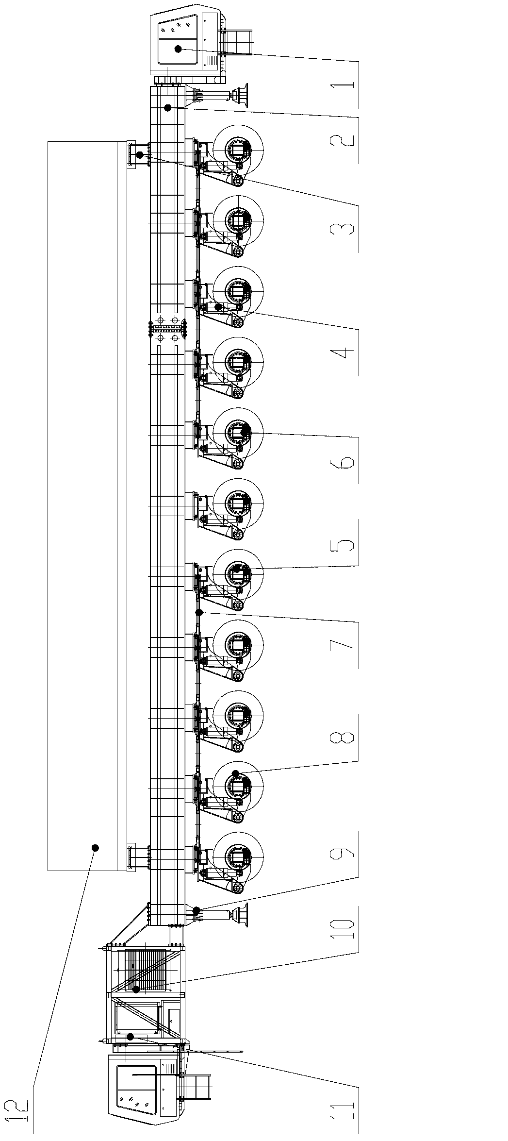
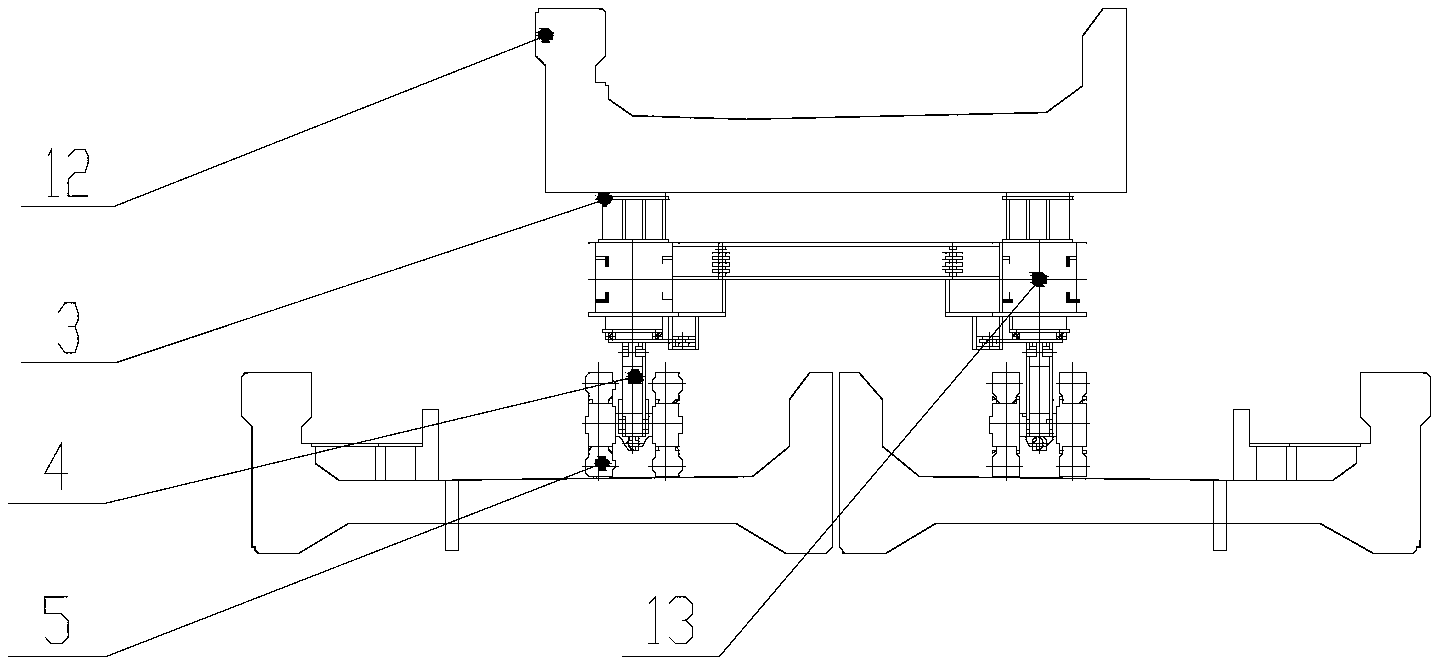
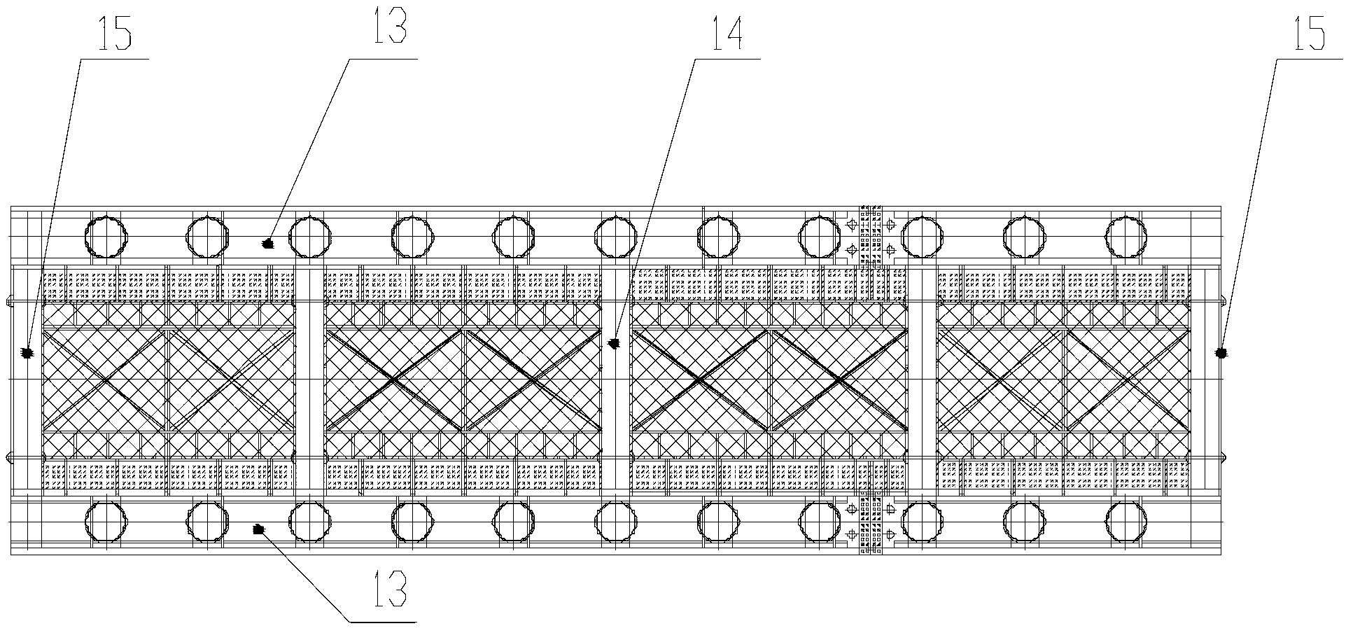
[0031] Such as Figure 1 to Figure 5As shown, the self-propelled trough beam transport vehicle of the present invention consists of a cab 1, a main structure 2, a support point 3, a power system 10, a hydraulic suspension 4, a drive axle 6, a driven axle 5, a steering system 7, and a braking system 8. The outrigger 9 and the electro-hydraulic control system 11 are composed of components such as the main structure 2, which is a force-bearing part. The main structure 2 includes a pair of symmetrically arranged main beams 13 and a cross beam 14 connected between the pair of main beams 13 The inverted "concave" main frame structure composed of end beams 15, the driving bridge 6 and the driven bridge 5 are connected to the lower ends of the main beams 13 on both sides of the main structure 2 through hydraulic suspension 4, and at the same time, the lower part of the main structure 2 is set Four hydraulic support legs 9, four bolsters 3 are arranged on the top, to carry the trough b...


PUM


Abstract

The invention discloses a self-propelled channel beam transport vehicle which is applicable to transporting channel beams of railways and comprises a main structure, hydraulic suspension systems, a multi-axis vehicle axle, a steering system, a braking system, a power system and an electro-hydraulic control system. The main structure comprises a pair of main beams and an inverted 'concave' main frame structure, the main beams are arranged in a bilateral symmetry manner, the inverted 'concave' main frame structure comprises crossbeams and end crossbeams which are connected between the main beams, two cabs are respectively connected to the front and the rear of the main structure, driving axles are arranged in the front of a vehicle body, driven axles are arranged at the rear of the vehicle body, suspension cylinders of the various hydraulic suspension systems positioned on the various driving axles on the left side and the right side of the longitudinal axle of the main structure are serially communicated with one another to form two groups respectively, all suspension cylinders of the various hydraulic suspension systems positioned on the various driven axles on the left side and the right side of the longitudinal axle of the main structure are serially communicated with one another to form two groups respectively, steering connecting rods of the driving axles are arranged in an inverted splay manner, and steering connecting rods of the driven axles are arranged in a splay manner. The self-propelled channel beam transport vehicle has the advantages that the self-propelled channel beam transport vehicle can run in two directions, is flexible in steering and high in field adaptability, the channel beams can be transported in an online manner, the transport efficiency can be greatly improved, and the under-bridge transport road construction cost is saved.

Description

technical field [0001] The invention relates to a vehicle used for bridge transportation, especially a channel beam transportation vehicle. Background technique [0002] With the continuous progress of my country's bridge construction technology, the current domestic railway bridge construction technology is developing in the direction of "centralized prefabrication, transportation and erection". At present, the box bridge construction equipment is relatively mature, mainly self-propelled tire transport vehicles for transportation operations, The bridge erecting machine is responsible for the construction of the girder, and the two types of equipment cooperate with each other to complete the erection task of the box girder. [0003] Channel beam is a new type of bridge suitable for windy areas. Its cross section is roughly U-shaped. It is used as the upper structure of railway bridges. It has the advantages of reducing noise, windproof and earthquake resistance. In the past,...

Claims


Application Information

Patent Timeline
Patent Type & Authority Applications(China)
IPC IPC(8): B60P3/022B62D7/00
Inventor 梁新华林国辉肖勇朱爱平刘海涛刘培勇李彬刘刚
Owner XINYUN ENG CO OF CHINA RAILWAY NO 2 ENG GRP CO LTD
Why Eureka
Try Eureka