

Independent primary air system provided with heat pipe exchanger and working method thereof
A technology of heat pipe heat exchanger and fresh air system, which is applied in the direction of ventilation system, heating and ventilation control system, heating and ventilation safety system, etc. It can solve the problems of reducing indoor air quality, occupying a large space, and cross-contamination, so as to improve indoor air quality. Air quality, low maintenance costs, and high heat exchange efficiency
- Summary
- Abstract
- Description
- Claims
- Application Information
AI Technical Summary
Problems solved by technology
Method used
Image

Examples
Embodiment
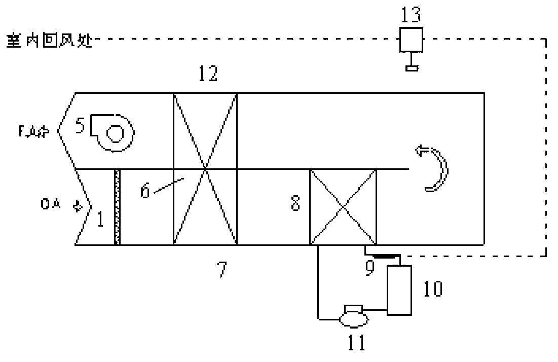
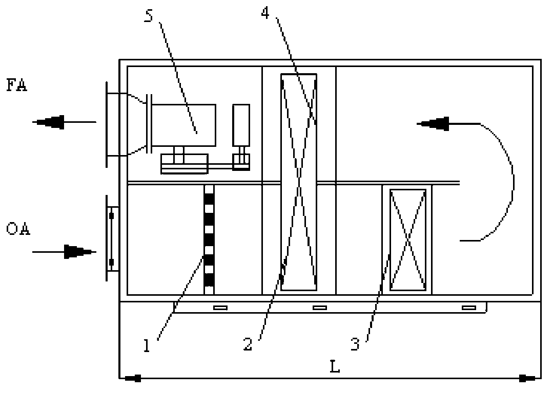
[0050] Embodiment: a kind of independent fresh air system that contains heat pipe heat exchanger (see Figure 2 to Figure 4 ), characterized in that it includes a pre-cooling unit 2, cooling and dehumidifying unit 3, reheating unit 4 and air supply unit 5; the pre-cooling unit 2, cooling and dehumidifying unit 3, reheating unit 4 and air supply unit 5 are installed in sequence Between the inlet and the outlet of the fresh air system; the air supply unit 5 is installed at the outlet of the fresh air system.
[0051] A filter unit 1 is installed at the inlet of the fresh air system. (See Figure 2 to Figure 4 )
[0052] The entrance and exit of the fresh air system are equipped with a damper actuator M and a differential air pressure switch ΔP; the air inlet side and the air outlet side of the precooling unit 2 and the reheating unit 4 are equipped with temperature and humidity sensors TH; the air supply unit 5 is connected to the frequency converter V; the fresh air system i...
PUM
 Abstract
Description
Claims
Application Information