Super resolution moving grating confocal imaging device and confocal imaging method

A technology of moving gratings and imaging devices, which is applied in the direction of using optical devices, measuring devices, instruments, etc., and can solve problems such as super-resolution moving grating imaging methods that have not yet appeared

Inactive Publication Date: 2013-08-21
HARBIN INST OF TECH
View PDF4 Cites 8 Cited by
  • Summary
  • Abstract
  • Description
  • Claims
  • Application Information

AI Technical Summary

Problems solved by technology

[0005] So far, there have been no reports on the introduction of super-r

Method used


Image

  • Super resolution moving grating confocal imaging device and confocal imaging method
  • Super resolution moving grating confocal imaging device and confocal imaging method
  • Super resolution moving grating confocal imaging device and confocal imaging method

Examples


specific Embodiment 1

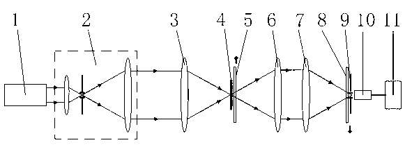
[0024] Both the modulation moving grating 5 and the demodulation moving grating 8 are one-dimensional sinusoidal gratings with diffraction orders of 0 and ±1, and they move at a constant speed at the same and opposite speeds at the conjugate positions of the object space and the image space. The converging angles of the objective lens 3 and the first collecting objective lens 6 are equal, that is, the numerical apertures in the air are equal, and NA=0.1 is selected in this embodiment.

[0025] In this example, in order to prevent the CTFs after the frequency band extension from overlapping, the spatial frequency of the grating used must satisfy

[0026] v 0 ≥4sin(α 0 ) / λ

[0027] Among them, v 0 is the spatial frequency of the grating, that is, the reciprocal of the spatial period of the grating; α 0 is the converging angle between the focusing objective lens 3 and the first collecting objective lens 6; λ is the wavelength of the illuminating light;

[0028] After filteri...

specific Embodiment 2

[0034] The difference between this embodiment and the specific embodiment 1 is that both the modulation moving grating 5 and the demodulation moving grating 8 are two-stage Dammann gratings with diffraction orders of 0, ±1 and ±2.

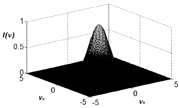
[0035] After filtering or integrating the signal processing, the normalized light intensity is:

[0036] I ( v , v x , v y ) = | [ 1 + 2 cos ( 4 v x ) + 2 cos ( 8 v x ) ...

specific Embodiment 3

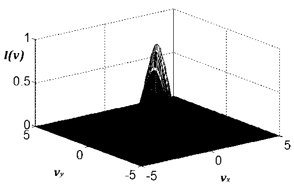
[0041] The difference between this embodiment and the specific embodiment 1 and the specific embodiment 2 is that the modulation moving grating 5 and the demodulation moving grating 8 adopted are two-dimensional sinusoidal gratings whose diffraction orders on the x-axis and y-axis are 0 and ±1, The two-dimensional sinusoidal grating has the same spatial frequency in the direction of the x-axis and the direction of the y-axis, and moves at a constant speed at the same and opposite speeds at the conjugate positions of the object space and the image space, and the speed in the y-axis direction is the x-axis direction 3 times the above.

[0042] After filtering or integrating the signal processing, the normalized light intensity is:

[0043] I ( v , v x , v y ) = | ...


PUM


Abstract

The invention belongs to the technical field of optical precision measurement, and provides a super resolution moving grating confocal imaging device and a confocal imaging method. The super resolution moving grating confocal imaging device is provided with a modulation moving grating, a demodulation moving grating and a signal processing device. The modulation moving grating and the demodulation moving grating are the same in type and in space cycle, and do linear motion or circumferential rotation at a conjugate position between an object space and an image space in constant speed in opposite directions. The signal processing device has a filtering or time integral function. The confocal imaging method includes the steps of using the modulation moving grating to carry out space-time modulation on light passing through samples in a confocal system, carrying out demodulation through the demodulation moving grating before the modulation light enters a light intensity detector, obtaining the instantaneous light intensity signals of scanning points, and carrying out signal processing to obtain the light intensity of the scanning points. The super resolution moving grating confocal imaging device and the confocal imaging method can improve spatial-cut-off frequency of the confocal system, even can enable implicit vector wave components to participate in imaging, broaden space frequency band width, and remarkably improve horizontal resolving ability, and is especially suitable for the measuring field for improving numerical aperture and achieving the measuring field of near-field implicit vector wave components imaging in a far field.

Description

technical field [0001] A super-resolution moving grating confocal imaging device and method belong to the technical field of optical precision measurement. Background technique [0002] Optical microscopy is a long-established and important non-destructive technique widely used in fields such as biology and materials science. Confocal microscopic measurement technology is a three-dimensional optical microscopy technology suitable for micron and submicron scale measurement. The tomographic capabilities of reflective confocal microscopy systems make them important in the field of 3D imaging. In the mid-to-late 1950s, the confocal microscope was invented by Minsky. In 1977, C.J.R. Sheppard and A.Choudhury first clarified that the confocal microscope system under the action of the dot pinhole mask, at the expense of the field of view, the lateral resolution Increased to 1.4 times that of ordinary microscopes with the same aperture. Since then, confocal microscopic measurement...

Claims


Application Information

Patent Timeline
IPC IPC(8): G01B9/00
Inventor 邹丽敏王宝凯陈彦均谭久彬
Owner HARBIN INST OF TECH
Why Eureka
Try Eureka