Mixed magnetic circuit inductor

A hybrid magnetic circuit, inductor technology, applied in the field of inductors

Inactive Publication Date: 2013-08-21
TAMURA CORP OF CHINA LTD +1
View PDF5 Cites 6 Cited by
  • Summary
  • Abstract
  • Description
  • Claims
  • Application Information

AI Technical Summary

Problems solved by technology

[0003] The present invention provides a hybrid magnetic circuit inductor that introduces a

Method used


Image

  • Mixed magnetic circuit inductor
  • Mixed magnetic circuit inductor
  • Mixed magnetic circuit inductor

Examples


Embodiment Construction

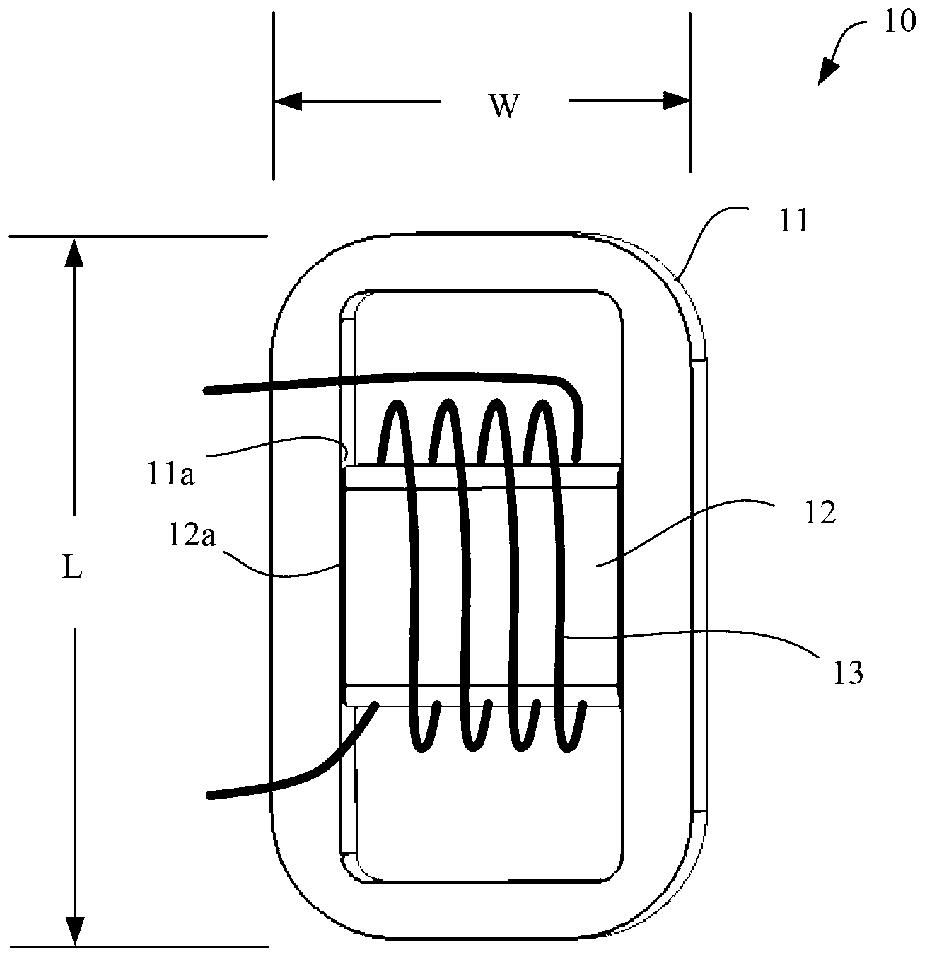
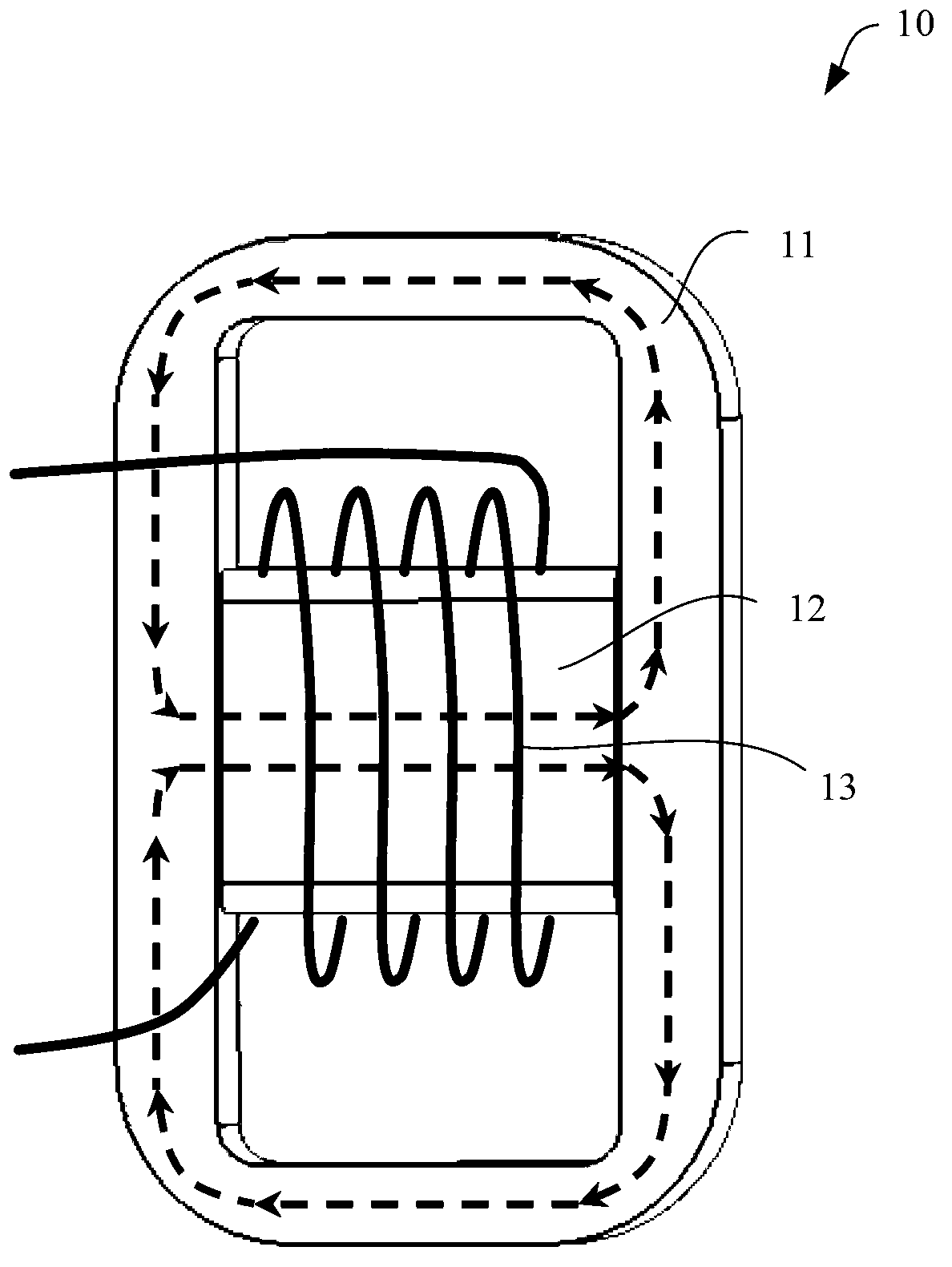
[0021] figure 1 A schematic structural diagram of the hybrid magnetic circuit inductor according to the first embodiment of the present invention is shown. refer to figure 1 As shown, the inductor 10 of this embodiment generally has a "day"-shaped structure. The magnetic core of the inductor 10 includes a square-shaped first magnetic core 11 on the periphery and a rod-shaped second magnetic core 12 inside. The length of the second magnetic core 12 may just be the width of the cavity of the first magnetic core 11 . In this way, both end surfaces 12 a of the second magnetic core 12 are in contact with the connection surfaces 11 a at corresponding positions on the inner sidewall of the first magnetic core 11 . In this embodiment, the connection surface 11 a of the first magnetic core 11 is exactly flat with the inner sidewall of the first magnetic core 11 .

[0022] The second magnetic core 12 can be exactly located in the center of the first magnetic core 11 , or it can be d...


PUM

PropertyMeasurementUnit
Widthaaaaaaaaaa
Magnetic permeabilityaaaaaaaaaa

Abstract

The invention relates to a mixed magnetic circuit inductor which comprises a magnetic core and a coil. The magnetic core comprises a first square-shaped magnetic core and a second square-shaped magnetic core which is located in the first magnetic core. Two end faces of the second magnetic core are respectively connected with a connecting face corresponding to the inner side wall of the first magnetic core, and the coil is wound on the second magnetic core. The first magnetic core is made of metal soft magnetism powder, and the magnetic permeability is less than 500H/m. The second magnetic core is made of ferrite, and the magnetic permeability is larger than 1500H/m. The ratio of the length, perpendicular to the direction of the second magnetic core, of the first magnetic core to the width, parallel to the direction of the second magnetic core, of the first magnetic core is larger than 1.2.

Description

technical field [0001] The invention relates to an inductor, in particular to a hybrid magnetic circuit inductor. Background technique [0002] Inductors are one of the basic components in circuits. Ordinary inductors are wound from coils. In order to increase the inductance and improve the quality factor of the coil, the coil will be wound on the magnetic core. The material of the magnetic core has a significant impact on the performance of the inductor. Among many materials, ferrite material is the more commonly used magnetic core material. Ferrite materials have higher magnetic permeability, which is conducive to making larger inductors. But ferrite materials also have the undesirable property of being relatively prone to magnetic saturation. To overcome this shortcoming, one solution is to use a larger size core, but this increases the cost of the inductor and is not conducive to the mounting of the inductor on the circuit board. Another solution is to draw an air ...

Claims


Application Information

Patent Timeline
IPC IPC(8): H01F27/255H01F1/147H01F41/02
Inventor 邵革良佐伯英人
Owner TAMURA CORP OF CHINA LTD
Why Eureka
Try Eureka