Photovoltaic power generation transformer

A photovoltaic power generation and transformer technology, applied in the direction of transformer/inductor magnetic core, transformer/inductor parts, transformer/inductor coil/winding/connection, etc. Low-level problems, to achieve the effect of strong heat dissipation and overload capacity, reduced loss, and complete balance of no-load current

Inactive Publication Date: 2013-08-21
SHANGHAI EAGTOP ELECTRONICS TECH
View PDF7 Cites 1 Cited by
  • Summary
  • Abstract
  • Description
  • Claims
  • Application Information

AI Technical Summary

Problems solved by technology

Therefore, as far as the transformer is concerned, the impedance is low, and it cannot filter out high-order harmonics. The harmonics must be eliminated by reactors.

Method used


Image

  • Photovoltaic power generation transformer

Examples


Embodiment Construction

[0016] In order to make the present invention more comprehensible, preferred embodiments are described in detail below with accompanying drawings.

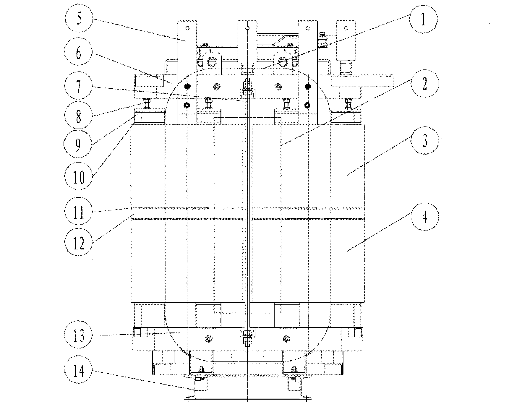
[0017] figure 1 A transformer for photovoltaic power generation provided by the present invention, each phase core of the transformer includes an upper iron yoke 1, a core column 2 and a lower iron yoke 13, and the upper iron yoke 1, core column 2 and lower iron yoke 13 adopt a continuous The silicon steel sheet is wound continuously to form a whole, the magnetic circuit of the core is closed, the magnetic flux direction is completely consistent with the grain orientation of the silicon steel sheet, the three-phase magnetic circuit lengths are completely equal, the sum of the three-phase magnetic circuit lengths is the shortest, and the three-phase magnetic circuits are completely symmetrical . Moreover, there is no seam between the core column 2 and the upper iron yoke 1 and the lower iron yoke 13, which fundamentally eliminates...


PUM


Abstract

The invention relates to a photovoltaic power generation transformer which is characterized by comprising a three-phase iron core arranged in a triangular mode. Each phase of the iron core is formed by coiling silicon steel sheets continuously, and a low-voltage coil and a high-voltage coil are respectively wound around the exterior of each phase of the iron core so that a three-phase coil arranged in the mode shaped like a Chinese character 'pin' can be formed. The low-voltage coil and the high-voltage coil of each phase are divided in the axial direction and are separated through a silicon pad and a divided magnetic circuit. Two ends of a vertically-pulling screw are respectively connected with one installing support. A locating structure locates the three-phase coil between the two installing supports, and leading-out bars connected with the three-phase coil are fixed on the installing supports. The photovoltaic power generation transformer is high in impedance, low in energy consumption and efficient.

Description

technical field [0001] The invention relates to an axially split high-impedance and low-loss transformer with a magnetic shunt, which is used in a photovoltaic power generation converter and belongs to the technical field of three-phase low-voltage AC transformers. Background technique [0002] Traditional photovoltaic power generation converters use a reactor-transformer combination structure or a transformer structure with auxiliary iron, the reactor is used for filtering, and the transformer is used for electrical isolation. Regardless of the structure, the transformer adopts radial splitting. Therefore, as far as the transformer is concerned, the impedance is low, and it cannot filter out high-order harmonics, and the harmonics must be eliminated by reactors. Contents of the invention [0003] The technical problem to be solved by the present invention is to provide a high-impedance, low-energy efficient transformer. [0004] In order to solve the above technical pro...

Claims


Application Information

Patent Timeline
IPC IPC(8): H01F27/26H01F27/245H01F27/30
Inventor 洪英杰
Owner SHANGHAI EAGTOP ELECTRONICS TECH
Why Eureka
Try Eureka