
Energy conversion system and method with negative-sequence current compensation mechanism

A technology of energy conversion system and negative sequence current, which is applied in the direction of electrical components, circuit devices, photovoltaic power generation, etc., can solve the problem of affecting system stability, the output of positive sequence current cannot meet the needs, and the energy conversion system cannot well meet the needs of the power grid. Design needs and other issues to achieve the effect of improving stability and reliable grid-connected power generation

Active Publication Date: 2013-08-21
GENERAL ELECTRIC CO
View PDF5 Cites 4 Cited by
  • Summary
  • Abstract
  • Description
  • Claims
  • Application Information

AI Technical Summary

Problems solved by technology

In this way, when a fault occurs in the power grid, such as a single phase fault (single phase fault) or the overall unbalance of the three-phase system, the resulting negative sequence current may affect the stability of the system
Specifically, a large negative sequence current may limit the positive sequence current output by the AC output terminal, which may cause the output of the positive sequence current to fail to meet the needs, and this makes the energy conversion system unable to meet the design needs of the grid

Method used


Image

  • Energy conversion system and method with negative-sequence current compensation mechanism
  • Energy conversion system and method with negative-sequence current compensation mechanism
  • Energy conversion system and method with negative-sequence current compensation mechanism

Examples


Embodiment Construction

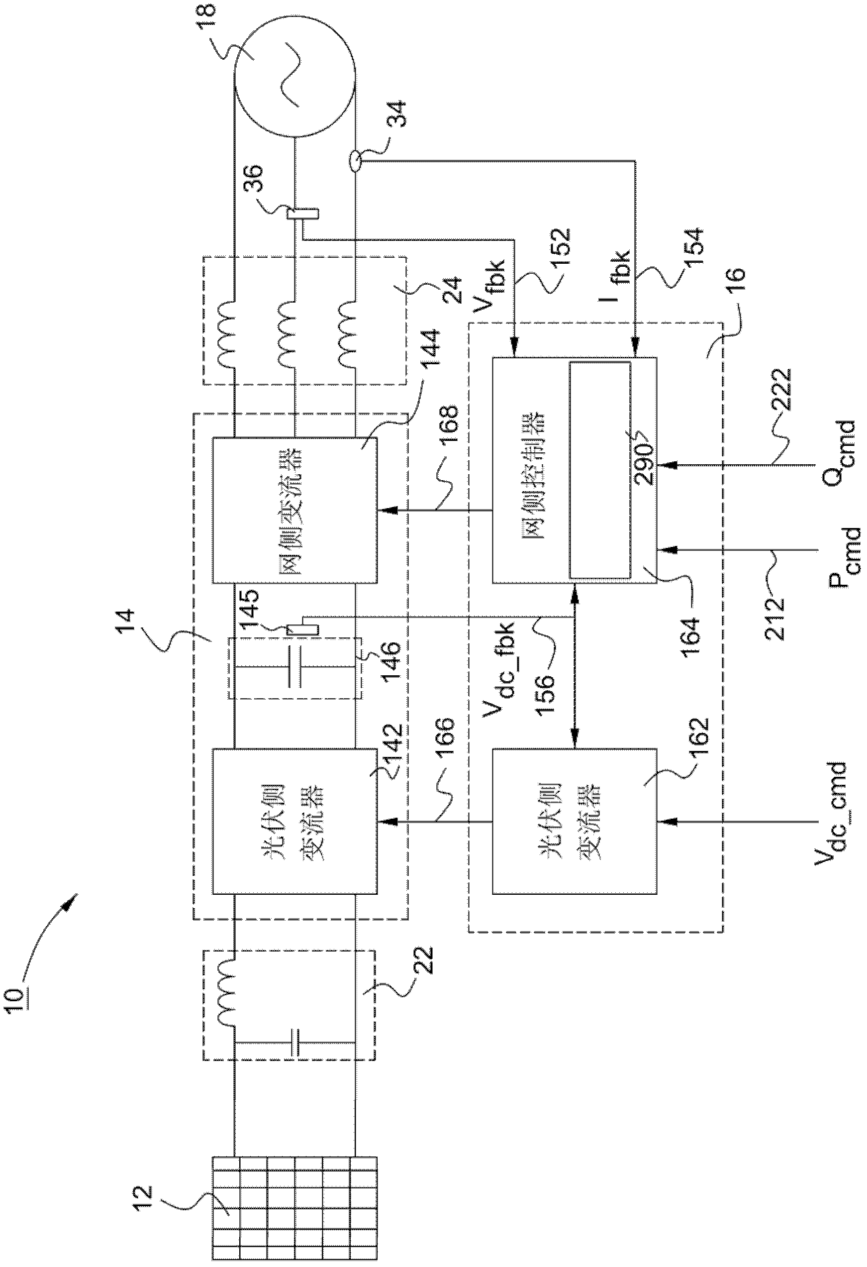
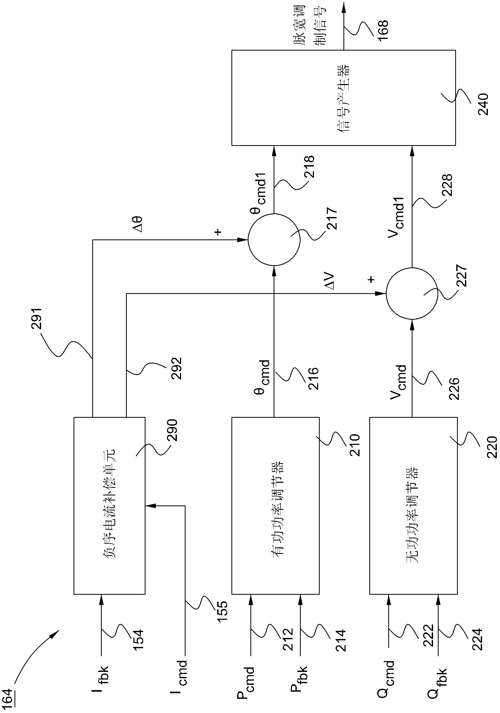
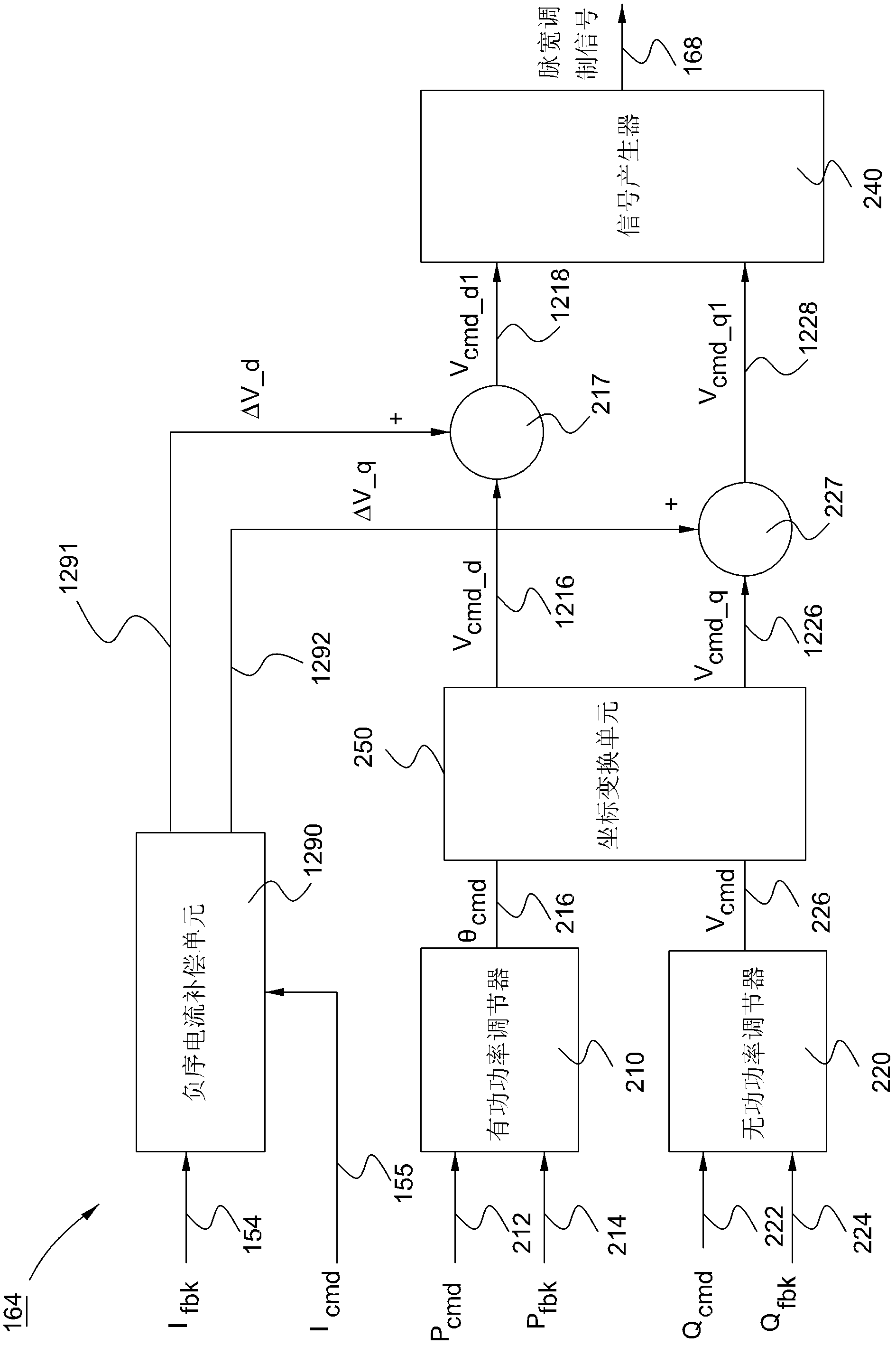
[0037] One or more embodiments disclosed in the present invention relate to a negative-sequence current compensation mechanism, which is used to deal with transient events or transient events or encounter fault conditions during the grid-connected power generation process of the energy conversion system or in the subsequent recovery process The resulting negative sequence current problem. The so-called "negative-sequence current compensation" here refers to tracking the current in the power grid in real time and providing instantaneous information of the negative-sequence current therein for negative-sequence current compensation. The so-called "transient or transient event" here refers to one or more events or conditions that cause signal disturbance on the grid side, for example, a single-phase fault or a three-phase unbalanced fault that occurs in the grid. More specifically, in one embodiment, the negative sequence current compensation mechanism described herein is impleme...


PUM


Abstract

The invention discloses an energy conversion system and method. The energy conversion system comprises a direct current bus, a converter module and a converter control module, wherein the direct current bus is used for receiving a direct current coming from a power source, and the converter module is used for converting the direct current on the direct current bus into an alternating current. The converter control module is used for producing a first command signal according to an active power command signal and an active power feedback signal, producing a second command signal according to a reactive power command signal and a reactive power feedback signal, and producing a first negative-sequence current correction signal and a second negative-sequence current correction signal according to a negative-sequence current command signal and a negative-sequence current feedback signal on a power grid, wherein the first negative-sequence current correction signal and the second negative-sequence current correction signal are used for compensating a negative-sequence current, and the first command signal and the second command signal are adjusted based on the first negative-sequence current correction signal and the second negative-sequence current correction signal respectively. The converter control module is further used for producing a control signal based on the adjusted first command signal and the adjusted second command signal so that the converter control module can be driven to operate under the function of the control signal.

Description

technical field [0001] The embodiments disclosed in the present invention relate to an energy conversion system and method for providing electric energy to a power system, and in particular to a negative-sequence current compensation mechanism and method for an energy conversion system. Background technique [0002] Basically, the share of electricity generated by renewable energy generation systems, such as photovoltaic power generation systems, is becoming more and more significant all over the world. A general photovoltaic power generation system includes one or more photovoltaic arrays, and each photovoltaic array includes a plurality of interconnected photovoltaic battery units, which can convert solar radiation energy into DC power. In order to realize the grid-connected power generation of the photovoltaic array, a converter module is usually used to convert the DC power generated by the photovoltaic array into AC power that can be transmitted by the grid. [0003] T...

Claims


Application Information

Patent Timeline
IPC IPC(8): H02J3/38H02J3/16H02J3/24
CPCH02J3/26Y02E40/50H02J2300/24H02J3/381Y02E10/56
Inventor 谭卓辉侯丹邬心慧公茂忠
Owner GENERAL ELECTRIC CO
Learn More