Shaft-end overhung piezoelectric cantilever beam electric generator

A cantilever beam, generator technology, applied in the direction of generator/motor, piezoelectric effect/electrostrictive or magnetostrictive motor, electrical components, etc., can solve the problem of reducing the axial vibration displacement of the piezoelectric vibrator and adapting the speed Low capacity, low power generation efficiency, etc., to achieve the effect of effective speed bandwidth, small influence of axial bending deformation, and strong power generation capacity

Inactive Publication Date: 2013-08-21
ZHEJIANG NORMAL UNIVERSITY
View PDF8 Cites 41 Cited by
  • Summary
  • Abstract
  • Description
  • Claims
  • Application Information

AI Technical Summary

Problems solved by technology

[0005] The invention provides a shaft-end-hanging piezoelectric cantilever generator, aiming at the power supply requirements of health monitoring systems for propellers, automobile wheels, cantilever shafts, etc. Rotary piezoelectric generators have low speed adaptability, and the centrifugal force of the magnet at high speeds will reduce the axial vibration displacement of the piezoelectric vibrator, or even have no vibration, and the power generation efficiency is low.

Method used


Image

  • Shaft-end overhung piezoelectric cantilever beam electric generator
  • Shaft-end overhung piezoelectric cantilever beam electric generator
  • Shaft-end overhung piezoelectric cantilever beam electric generator

Examples


Embodiment Construction

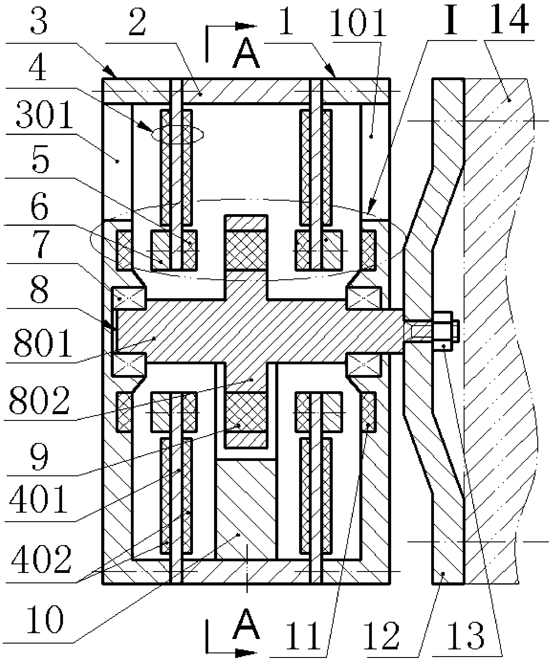
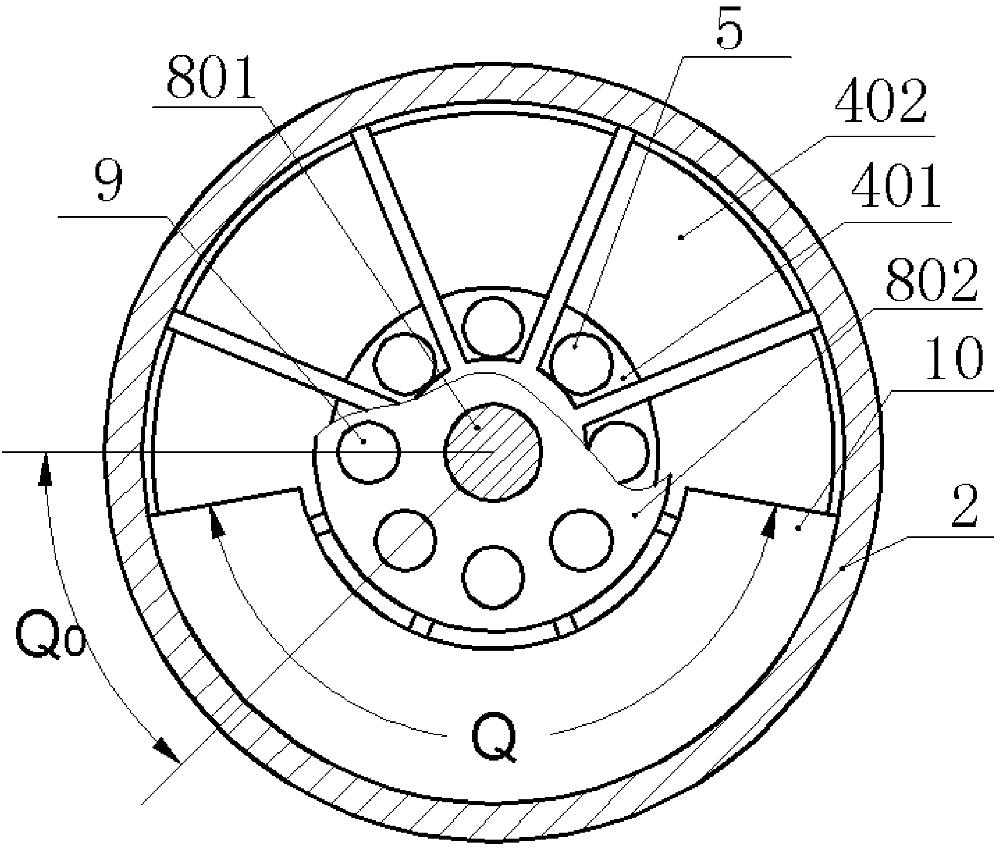
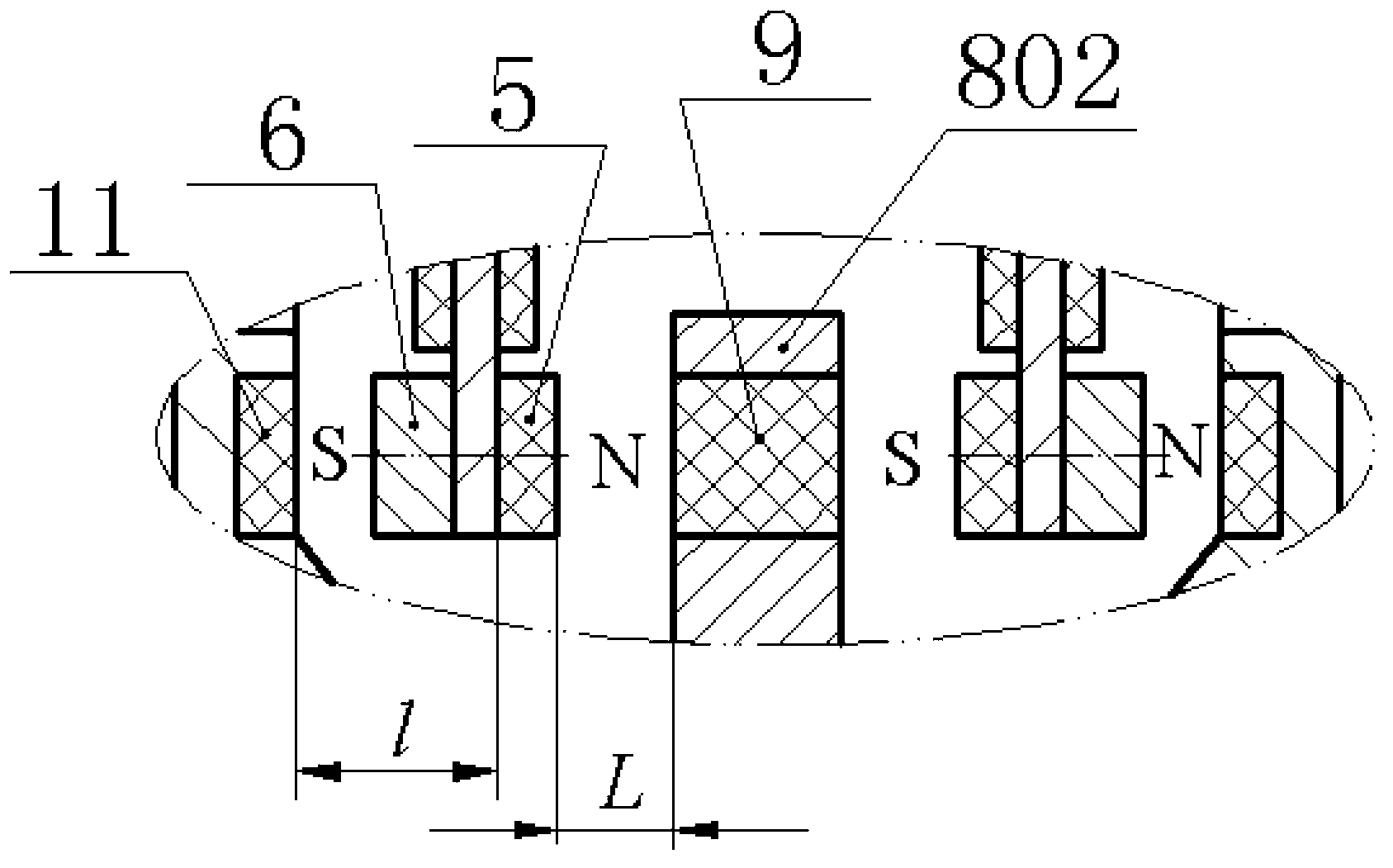
[0016] The left end cover 3 and the right end cover 1 are respectively installed on the two ends of the housing 2 by screws, and the inner lower side of the housing 2 is equipped with a semi-circular counterweight 10 by screws; the upper part of the left end cover 3 and the right end cover 1 A lightening hole 301 and a lightening hole two 101 are respectively provided, and the inside of the bottom wall of the left end cover 3 and the right end cover 1 are inlaid with a circular magnet 11 and a bearing 7; the left end cover 3 and the right end cover 1 are inlaid with Metal substrates 401 are crimped between the housings 2, and the metal substrates 401 and the piezoelectric wafers 402 bonded on their sides form sector-shaped piezoelectric vibrators 4, and the free ends of the piezoelectric vibrators 4 are mounted with round Shaped magnet 2 5 and frequency modulation mass block 6, the rotating shaft 801 of rotor 8 is installed on the left end cover 3 and the right end cover 1 by b...


PUM


Abstract

The invention relates to a shaft-end overhung piezoelectric cantilever beam electric generator, and belongs to the technical field of new energy resources and power generation. A left end cover and a right end cover are respectively installed at two ends of a shell body through screws. A semi-annular balancing weight is installed on the lower side of the interior of the shell body through a screw. The upper portion of the left end cover and the upper portion of the right end cover are respectively provided with a lightening hole. A magnet I and a bearing are embedded in the inner side of the bottom wall of the left end cover. A magnet I and a bearing are embedded in the inner side of bottom wall of the right end cover. A piezoelectric vibrator is arranged between the left end cover and the shell body in a compression joint mode. A piezoelectric vibrator is arranged between the right end cover and the shell body in a compression joint mode. A magnet II and a frequency-modulation mass block are installed at the free end of each piezoelectric vibrator. A rotating shaft of a rotor is installed on the left end cover and the right end cover through bearings. A connecting disc is installed at one end of the rotating shaft through a nut. A magnet III is embedded in a rotating disc of the rotor. The shaft-end overhung piezoelectric cantilever beam electric generator has the advantages that the piezoelectric vibrators are motivated for electric generation and external fixing and supporting are not needed; the shaft-end overhung piezoelectric cantilever beam electric generator is an integrated type individual component, so that the structure of a rotating body does not need to be changed, and the shaft-end overhung piezoelectric cantilever beam electric generator is convenient to install and maintain; the shaft-end overhung piezoelectric cantilever beam electric generator is high in reliability, strong in power generation capacity, and wide in velocity zone.

Description

technical field [0001] The invention belongs to the technical field of new energy and power generation, and in particular relates to a piezoelectric cantilever beam generator suspended from a shaft end, which is used for power supply of a health monitoring system without a fixedly supported rotating body. Background technique [0002] In order to meet the power supply requirements of the health monitoring system of rotating bodies such as helicopter propellers, automobile tires, aeroengines, high-speed trains, oil and gas drill spindles and their bearing components, domestic and foreign scholars have proposed various forms of rotary piezoelectric and electromagnetic micro power generation. machine. Relatively speaking, the rotary electromagnetic generator is very mature and has been widely used, but it is not suitable for powering the wireless sensor monitoring system because of the electromagnetic interference generated during the power generation process. In addition, the ...

Claims


Application Information

Patent Timeline
Patent Type & Authority Applications(China)
IPC IPC(8): H02N2/18
Inventor 程光明阚君武杨振宇曾平王淑云
Owner ZHEJIANG NORMAL UNIVERSITY
Why Eureka
Try Eureka