Apparatus for CT-RI and nuclear hybrid imaging, cross calibration, and performance assessment

A CT imaging and nuclear imaging technology, which is applied in the fields of radiological diagnosis instruments, applications, medical science, etc., can solve problems such as misregistration, and achieve the effect of improving workflow and reducing image registration errors.

Inactive Publication Date: 2013-08-21
KONINKLIJKE PHILIPS ELECTRONICS NV
View PDF6 Cites 19 Cited by
  • Summary
  • Abstract
  • Description
  • Claims
  • Application Information

AI Technical Summary

Problems solved by technology

Although positioning the patient in the same position by moving the patient a known longitudinal distance for more than one exam reduces the possibil

Method used


Image

  • Apparatus for CT-RI and nuclear hybrid imaging, cross calibration, and performance assessment
  • Apparatus for CT-RI and nuclear hybrid imaging, cross calibration, and performance assessment
  • Apparatus for CT-RI and nuclear hybrid imaging, cross calibration, and performance assessment

Examples


Embodiment Construction

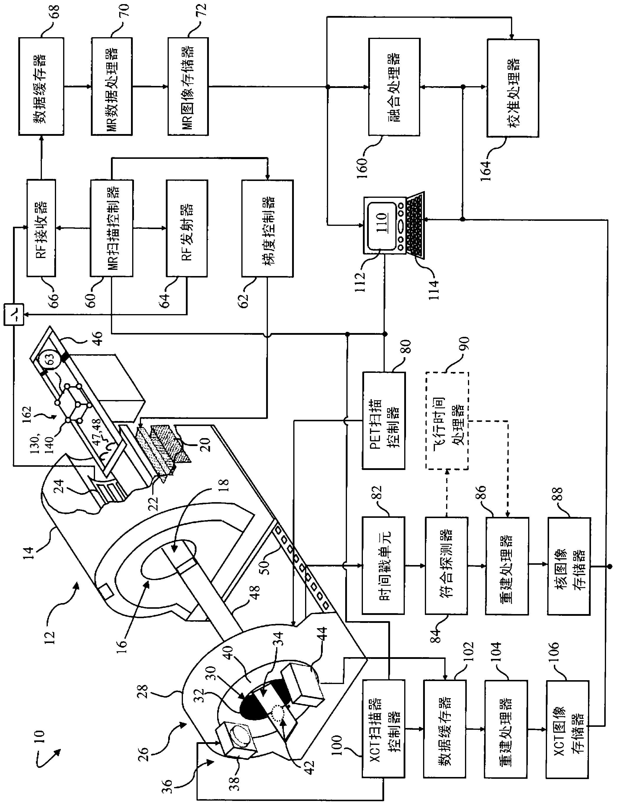
[0023] refer to figure 1 , the diagnostic imaging system 10 performs X-ray computed tomography (CT) and nuclear imaging, such as PET or SPECT, as well as magnetic resonance imaging and / or spectroscopic analysis. The diagnostic imaging system 10 includes a first imaging system, in the illustrated embodiment a magnetic resonance scanner 12 , housed within a first gantry 14 . The first patient-receiving bore 16 defines a first or MR examination region 18 of the MR scanner 12 . The MR scanner includes a main magnet 20 that generates a temporally uniform B 0 field. The gradient magnetic field coil 22 arranged adjacent to the main magnet is used to move along with respect to B 0 Selected axes of the magnetic field generate magnetic field gradients to spatially encode the magnetic resonance signal, generate magnetization destroying field gradients, and the like. Magnetic field gradient coils 22 may include coil segments configured to generate magnetic field gradients in three ort...


PUM


Abstract

A multiple modality imaging system (10) includes a MR scanner (12) which defines an MR imaging region (18), a nuclear imaging scanner (26) which defines a nuclear imaging region (34), an CT scanner (36) which defines an CT imaging region (42). Each scanner (12, 26, 36) having a longitudinal axis along which a common patient support (46) moves linearly through the MR, nuclear, and CT imaging regions (18, 34, 42). A marker (130, 140, 150), for use with the system (10), includes a radio-isotope marker (132) which is imageable by the nuclear imaging scanner (26) and the CT scanner (36) surrounded by a flexible silicone MR marker (134) which is imageable by the MR scanner (12) and the CT scanner (36). A calibration phantom(162), for use with the image scanner (10), includes a plurality of the markers (130, 140, 150) supported by a common frame having a known and predictable geometry.

Description

technical field [0001] The present invention relates to diagnostic imaging systems and methods. The invention is particularly suitable for cross-calibration, performance assessment and image registration applications incorporating multimodal imaging systems combining MRI, CT and one of PET or SPECT, but may also be used in other diagnostic or therapeutic systems. Background technique [0002] In a multimodal imaging system, two different sensing modalities are used, e.g. a nuclear imaging scanner like PET or SPECT coupled with an anatomical scanner like CT, XCT, MRI, etc. to localize or measure object space different components in. For example, PET and SPECT scanners generate functional images indicative of metabolic activity in the body, rather than images of surrounding anatomy. CT scans allow doctors to see the inner structures of hard tissues within the body, such as bones; while MRI scans visualize soft tissue structures such as the brain, spine, vasculature, joints, ...

Claims


Application Information

Patent Timeline
IPC IPC(8): A61B6/03A61B5/055A61B6/00A61B19/00
CPCA61B6/032A61B6/037A61B6/4417A61B6/583A61B2017/00707A61B2017/00725A61B2090/392A61B2090/3995A61B90/39A61B2090/3954A61B2090/3966A61B5/0035
Inventor N·欧嘉M·A·莫里希
Owner KONINKLIJKE PHILIPS ELECTRONICS NV
Why Eureka
Try Eureka