DPF system

A diesel and particle filter technology, applied in the field of DPF system, can solve the problems of reducing dosage deviation, unstable exhaust gas temperature, and inability to perform stable temperature control, etc.

Active Publication Date: 2013-08-21
ISUZU MOTORS LTD
View PDF8 Cites 21 Cited by
  • Summary
  • Abstract
  • Description
  • Claims
  • Application Information

AI Technical Summary

Problems solved by technology

[0011] The causes of the flow rate deviation of the above-mentioned exhaust pipe injector are manufacturing deviation of the injector and clogging due to aging.
When these deviations become large, even if the feedback (FB) control of the injection amount based on the exhaust gas temperature is performed, the correction limit may be exceeded, the exhaust injection am

Method used


Image

  • DPF system
  • DPF system
  • DPF system

Examples


Embodiment Construction

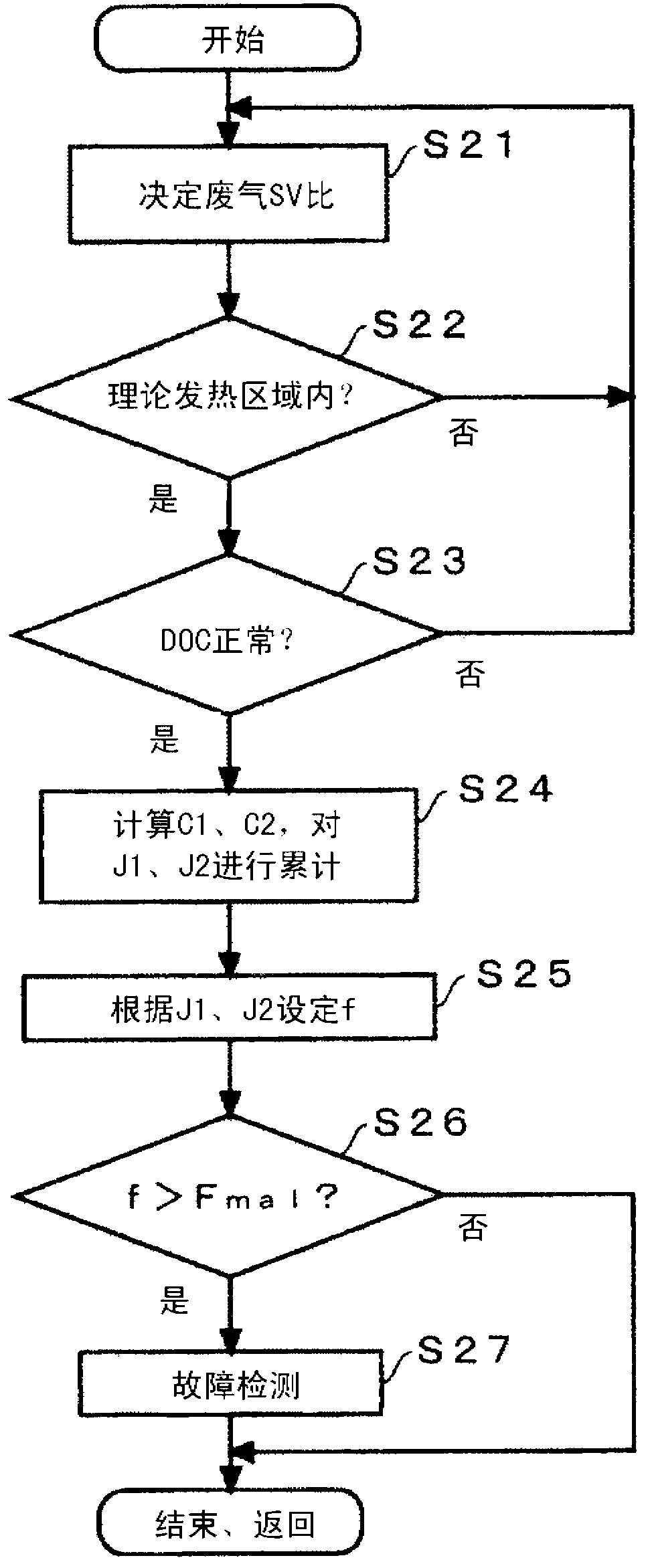
[0024] Hereinafter, preferred embodiments of the present invention will be described based on the drawings.

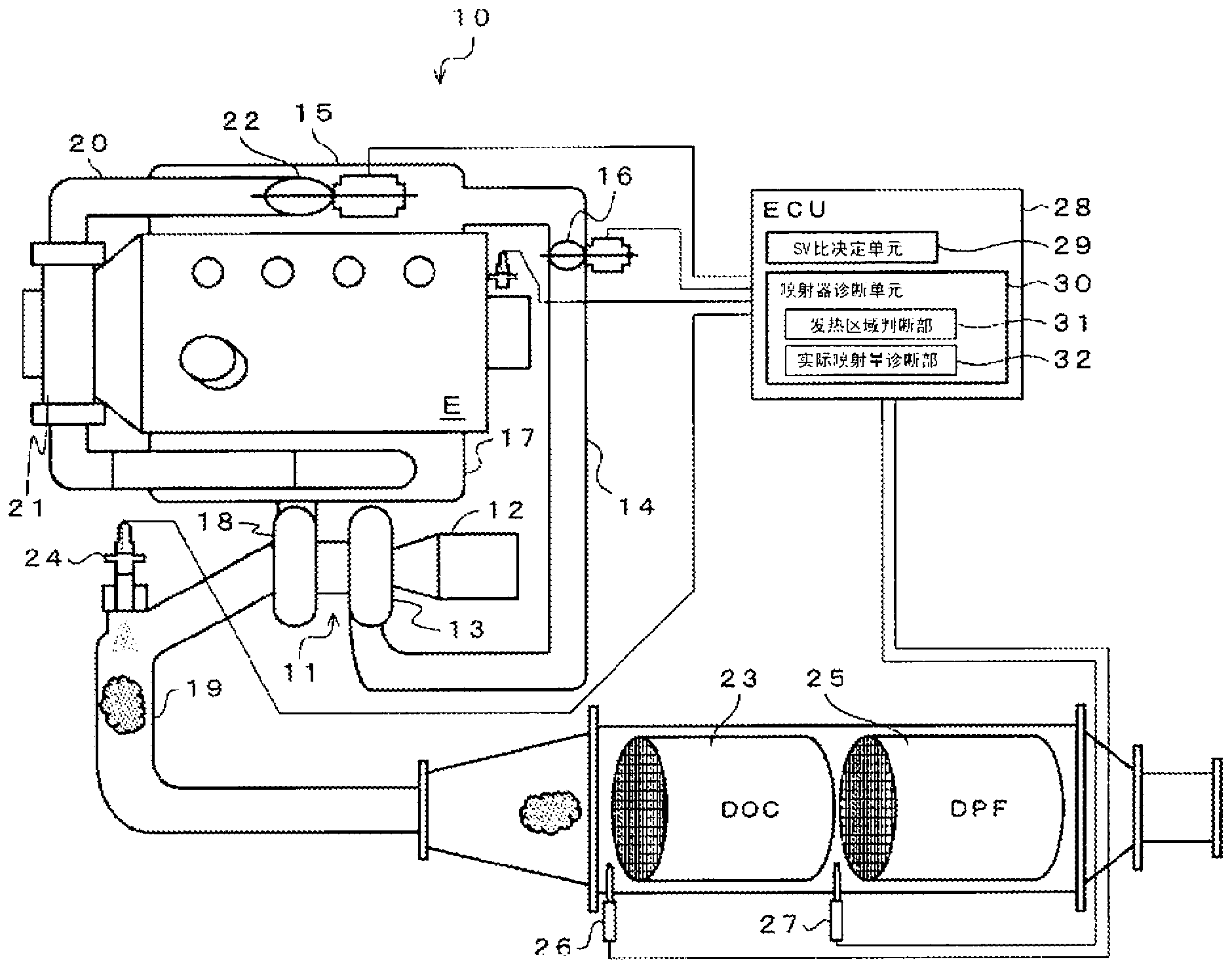
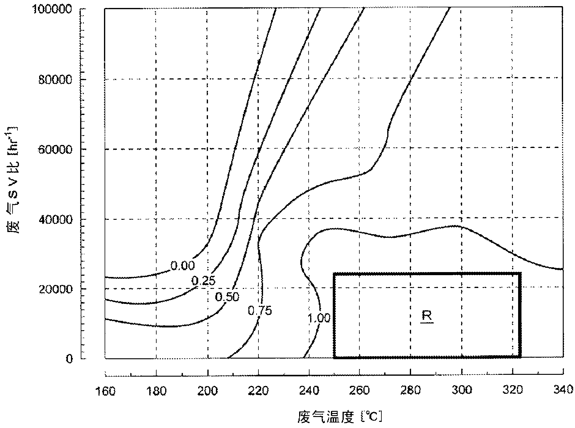
[0025] figure 1 It is a schematic diagram showing the structure of the DPF system of this embodiment.

[0026] The DPF system 10 of the present embodiment is equipped with a turbocharger 11, the air sucked in from the air cleaner 12 is compressed by the compressor 13 of the turbocharger 11, and is pressure-fed to the intake passage 14, and the air from the intake passage 14 The intake manifold 15 connected to 14 supplies the engine E. An intake valve 16 for adjusting the amount of air supplied to the engine E is provided on the intake passage 14 .

[0027] Exhaust gas exhausted from the engine E flows into and drives a turbine 18 of the turbocharger 11 from an exhaust manifold 17 , and is exhausted to an exhaust pipe 19 .

[0028] The DPF system 10 includes: an EGR pipe 20 connecting the intake manifold 15 and the exhaust manifold 17; an EGR cooler 21 for cooling th...


PUM


Abstract

Provided is a DPF system that can perform DPF regeneration with an appropriate exhaust-injection amount even if the injection amount changes due to age-related deterioration or manufacturing variability of an exhaust-pipe injector. Said DPF system (10) is provided with: temperature sensors (26 and 27) that are provided at the entrance and exit of a DOC (23) and measure the DOC entrance temperature and DOC exit temperature during forced DPF regeneration; a surface-area-to-volume ratio determination means (29) that determines an exhaust-gas surface-area-to-volume ratio by measuring the flow rate of exhaust gas during forced DPF regeneration; and an injector diagnosis means (30) to which the temperatures measured by the temperature sensors (26 and 27) and the value determined by the surface-area-to-volume ratio determination means (29) are inputted. Said injector diagnosis means has: a heat-generation region determination unit (31) that determines whether or not the inputted values lie within a theoretical heat-generation region; and an actual-injection-amount diagnosis unit (32) that diagnoses the amount of decrease in the actual injection amount of an exhaust-pipe injector (24) if the temperatures measured by the temperature sensors (26 and 27) and the value determined by the surface-area-to-volume ratio determination means (29) do lie within the aforementioned theoretical heat-generation region.

Description

technical field [0001] The invention relates to a DPF system, which collects particulate matter from the exhaust gas of a diesel engine through the DPF, and burns and removes it through exhaust pipe injection. Background technique [0002] In recent years, a DPF (Diesel Particulate Filter: Diesel Particulate Filter) device for purifying PM (Particulate Matter: Particulate Matter) from diesel engine exhaust gas has been developed. In addition, developed for the purification of NO in exhaust gas x LNT (Lean NO x Trap: NOx storage device) catalyst. In the DPF system that connects such an exhaust gas purification device to the exhaust pipe, when the purification efficiency of the purification device decreases, unburned fuel is added to the exhaust gas, and the DOC (Diesel Oxidation Catalyst: Diesel Oxidation Catalyst: diesel oxidation) installed in the exhaust pipe Catalyst) to oxidize and burn the PM accumulated in the DPF through high-temperature exhaust gas (DPF forced re...

Claims


Application Information

Patent Timeline
IPC IPC(8): F01N3/023F01N3/025F01N3/029F01N3/20F01N3/36B01D46/42
CPCB01D46/448B01D2279/30F01N3/0253F01N2560/06F01N2900/06F01N2900/1821F01N2550/05F01N2610/03F01N2900/0418F01N2900/1404F01N11/002Y02T10/40B01D46/84
Inventor 长冈大治中田辉男游座裕之
Owner ISUZU MOTORS LTD
Why Eureka
Try Eureka