Passive B1 field shimming

A passive shimming and excitation field technology, used in magnetic resonance measurement, instruments, measurement devices, etc., can solve problems such as lack of uniformity artifacts, and achieve the effect of improving excitation uniformity and signal-to-noise ratio.

Active Publication Date: 2013-08-21
KONINKLIJKE PHILIPS ELECTRONICS NV
View PDF3 Cites 5 Cited by
  • Summary
  • Abstract
  • Description
  • Claims
  • Application Information

AI Technical Summary

Problems solved by technology

B 1 Lack of uniformity causes artifacts in acquired images or other magnetic resonance results

Method used


Image

  • Passive B1 field shimming
  • Passive B1 field shimming
  • Passive B1 field shimming

Examples


Embodiment Construction

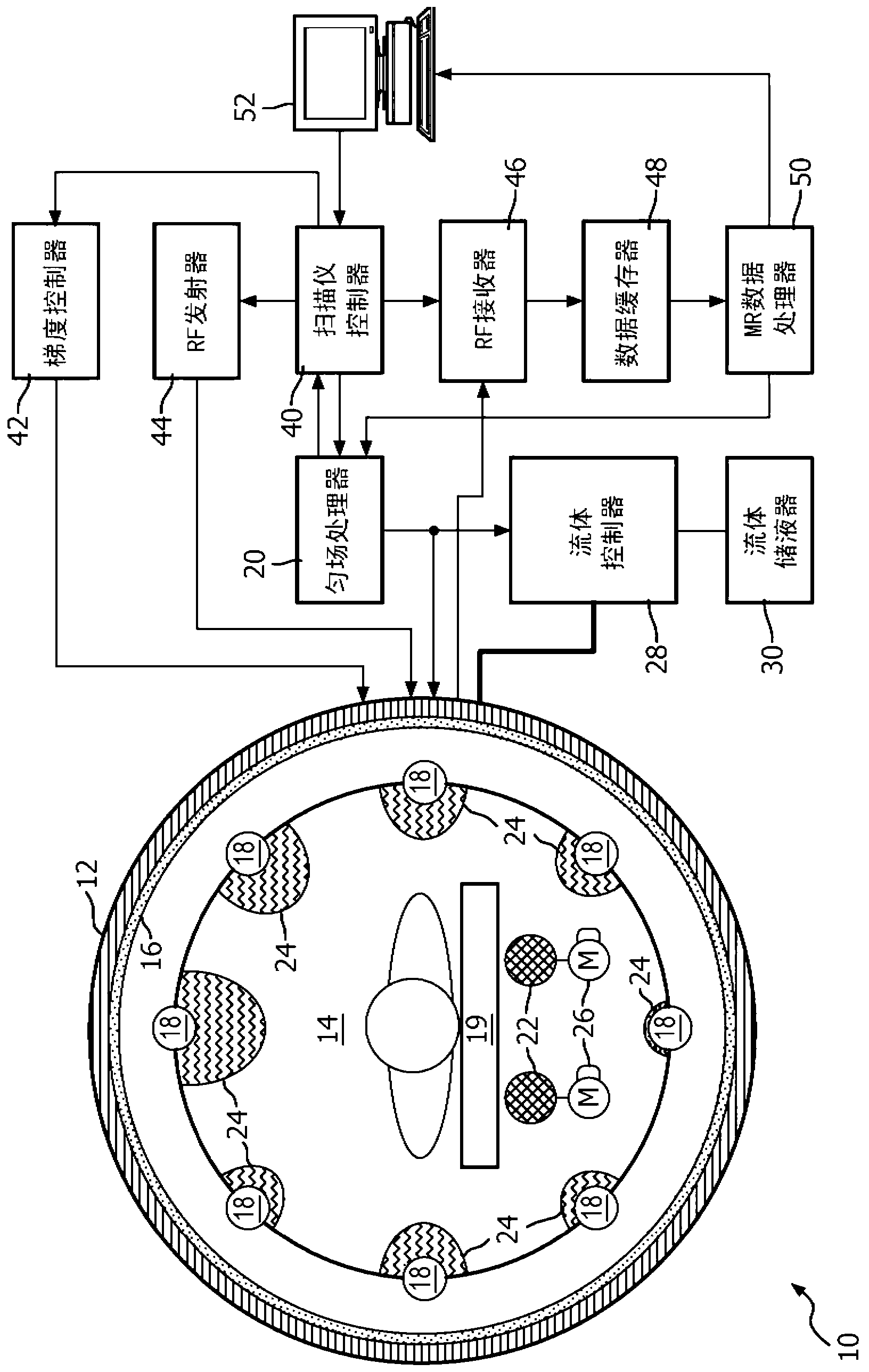
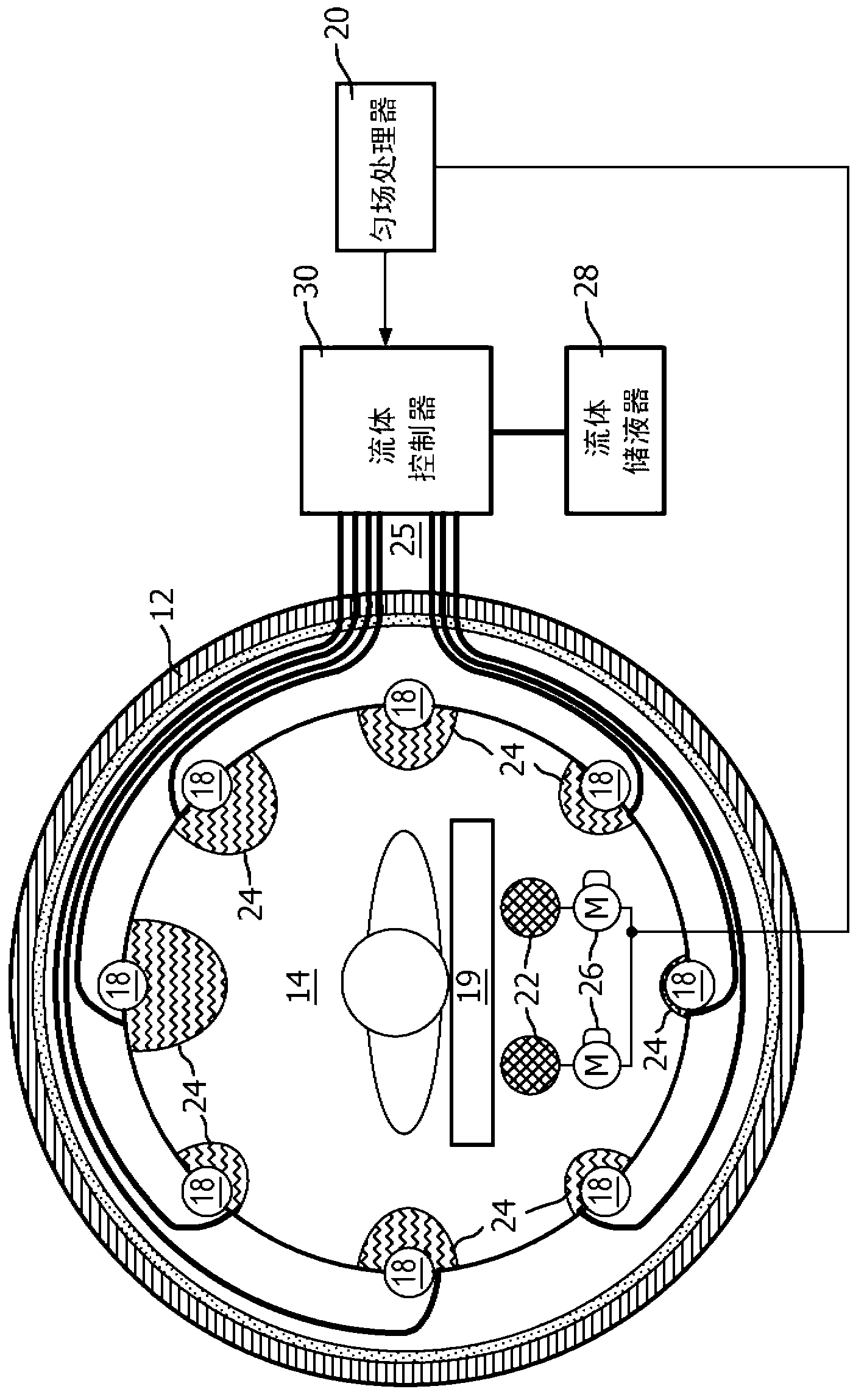
[0020] refer to figure 1 with figure 2 , a magnetic resonance (MR) imaging system 10 includes a main magnet 12 that produces a spatially and temporally uniform B of at least 3 Tesla across an examination region 14 0 field. The main magnet can be a ring or hole magnet, etc. The gradient magnetic field coil 16 arranged adjacent to the main magnet is used to 0 The magnetic field generates magnetic field gradients along selected axes for spatially encoding the magnetic resonance signals, for generating magnetization-spoiling field gradients, and the like. The magnetic field gradient coils 16 may include coil segments configured to generate magnetic field gradients in three orthogonal directions, typically the longitudinal or z direction, the transverse or x direction, and the vertical or y direction.

[0021] A radio frequency (RF) coil assembly, such as a whole body radio frequency coil, is arranged adjacent to the examination zone. The RF coil assembly may include a plural...


PUM


Abstract

Coil elements (18) generate a B1 excitation field in an examination region (14), which B1 excitation field is distorted by patient loading (e.g., wavelength effects). Passive shimming elements (22, 24) are disposed between the coil elements and the subject in order to improve the B1 field uniformity. In one embodiment, passive shimming elements include one or more dielectric rods (55) disposed below the subject which generate no substantial MR proton signal and which have a permittivity of at least 100 and preferably greater than 500. In another embodiment, tubes (24) adjacent each coil element are supplied with a dielectric liquid, a thickness of the dielectric liquid between the coil element and the subject adjusting a phase of the B1 field generated by the coil element. Active B1 shimming may be combined with passive shimming elements (22, 24) to effect an improved RF field homogeneity result.

Description

technical field [0001] This application relates to the field of magnetic resonance. It is particularly suitable for applications involving radio frequency (RF) coils and the modification of magnetic fields generated therefrom. However, it is also applicable to magnetic resonance imaging, spectroscopy and other NMR techniques. Background technique [0002] The load from the patient under examination makes B 1 The excitation field is distorted. This distortion varies with the size and shape of the subject and the operating radio frequency. This distortion becomes particularly severe above 3 Tesla, which has an operating radio frequency of about 128 MHz for hydrogen. B 1 The lack of uniformity causes artifacts in the resulting images or other magnetic resonance results. [0003] The present application provides new and improved systems and methods that overcome the above-mentioned problems and others. Contents of the invention [0004] According to one aspect, a magnet...

Claims


Application Information

Patent Timeline
Patent Type & Authority Applications(China)
IPC IPC(8): G01R33/34G01R33/54
CPCG01R33/246G01R33/34G01R33/34076G01R33/543G01R33/5659G01R33/3873
Inventor Z·翟M·A·莫里希P·R·哈维M·富德勒
Owner KONINKLIJKE PHILIPS ELECTRONICS NV
Why Eureka
Try Eureka