Dynamic evaluation of the optical multiplex section per-channel pre-emphasis power

A pre-emphasis and channel technology, applied in the field of optical networks, can solve problems such as deviation

Active Publication Date: 2013-08-21
WSOU INVESTMENTS LLC
View PDF7 Cites 8 Cited by
  • Summary
  • Abstract
  • Description
  • Claims
  • Application Information

AI Technical Summary

Problems solved by technology

[0006] Therefore, when these differences are particularly severe (i.e., in the case of OMS with large spans and amplifie...

Method used


Image

  • Dynamic evaluation of the optical multiplex section per-channel pre-emphasis power
  • Dynamic evaluation of the optical multiplex section per-channel pre-emphasis power
  • Dynamic evaluation of the optical multiplex section per-channel pre-emphasis power

Examples


Embodiment Construction

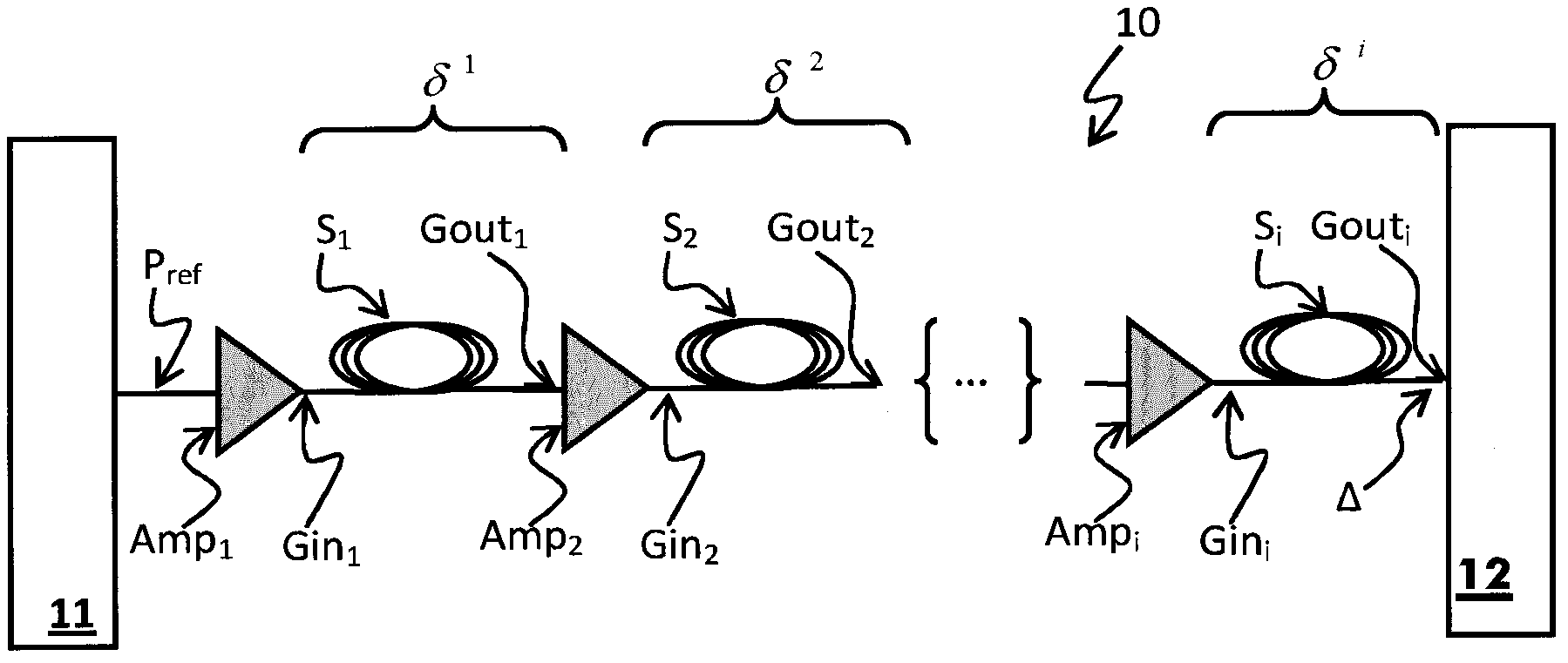
[0040] figure 1 A typical optical multiplex section (OMS) 10 is shown comprising a wavelength selective switch (WSS) 11 and a number of fiber spans S 1 , S 2 ,...,S i , each span consists of an optical amplifier Amp 1 , Amp 2 ,...,Amp i separated. Notice, figure 1 Only the OMS in a single direction is shown. Usually the OMS is bi-directional and includes two span sequences between each WSS 11, 12, one in each direction.

[0041] Although figure 1 shows multiple spans S of similar length 1 , S 2 ,...,S i , it should be realized that the length of each span can vary significantly. Moreover, the optical amplifier Amp 1 , Amp 2 ,...,Amp i They can also differ in design, quality and output power. The above changes affect the degradation of the signal in different ways.

[0042] in such as figure 1 In the system shown, there are three main causes of power error per channel; namely, tilt, gain error, and peak-to-peak fluctuation. Because the losses due to tilt are ...


PUM


Abstract

An apparatus for and a method of pre-emphasis the launch power profile of a section in an optical network are provided. The method comprises the steps of measuring the output power at the output of the section, determining the predicted output power associated with a flat launch power profile using design characteristics of the section and determining the total power deviation between the measured output power and the predicted output power. The method also comprises the steps of determining the signal to noise ratio deviation and the nonlinear phase shift deviation as a function of the total power deviation, and pre-emphasis the launch power profile based on a function of the calculated signal to noise ratio deviations of each span and the calculated nonlinear phase shift deviations of each span, such that the sum of the nonlinear phase shift deviations and the sum of the signal to noise ratio deviations of each channel are reduced by an equal amount.

Description

technical field [0001] The invention relates to the field of optical networks. More specifically, the invention relates to the optimization of the pre-emphasis power per channel in an optical multiplex section. Background technique [0002] Many optical networks include wavelength selective switches (WSS) interconnected by optical multiplex sections (OMS), each comprising multiple spans of optical fiber. In such a network, signals of different wavelengths called channels are multiplexed together and transmitted through the same OMS. The fiber spans that make up the segments of the OMS are usually separated by optical amplifiers that will act as repeaters, receiving a degraded signal at the end of the first span and sending a stronger signal at the beginning of the next span. [0003] This re-amplification process, while extending the length of the OMS, itself introduces some errors into the signal. Also, the amount and impact these errors will have will vary depending on ...

Claims


Application Information

Patent Timeline
IPC IPC(8): H04B10/293H04B10/294H04B10/564H04J14/02
CPCH04B10/2935H04B10/294H04B10/564H04J14/0221H04B10/291H04B10/50H04J14/02H04B10/07955
Inventor J-L·奥热
Owner WSOU INVESTMENTS LLC
Why Eureka
Try Eureka