Heat pipe bending method and heat pipe bending production device

A technology for manufacturing devices and heat pipes, which is applied in the fields of heat pipe bending methods and heat pipe bending manufacturing devices, can solve problems such as inability to use mandrel rods, section distortion, and difficult processing, and achieve the goals of preventing distortion, facilitating control, and improving the wrinkle limit Effect

Inactive Publication Date: 2013-08-28
SUN YAT SEN UNIV
View PDF8 Cites 12 Cited by
  • Summary
  • Abstract
  • Description
  • Claims
  • Application Information

AI Technical Summary

Problems solved by technology

[0007] Because the heat pipe is closed and hollow, and the mandrel cannot be used in the bending process, it is difficult to process it according to the conventional pipe bending process
The existing bending forming often appears as figure 1 The wrinkling phenomenon shown, figure 2 The depression phenomenon shown, image 3 cross-sectional distortion

Method used


Image

  • Heat pipe bending method and heat pipe bending production device
  • Heat pipe bending method and heat pipe bending production device
  • Heat pipe bending method and heat pipe bending production device

Examples


Embodiment 1

[0031] Such as Figure 4 As shown, a heat pipe bending manufacturing device includes a heating system for heating the heat pipe 50, a mechanical bending system for bending the heat pipe 50, a cooling system for cooling the bent heat pipe 50, and controlling the above-mentioned A control system in which the system performs sequential work.

[0032] The mechanical bending system includes a frame (not shown in the figure), a driving mechanism (not shown in the figure), a support mold 11 , a clamping mold 12 and a bending mold 13 . The supporting mold 11 is fixed on the frame, and the clamping mold 12 and the bending mold 13 are all connected on the driving mechanism. The clamping die 12 and the bending die 13 are driven to swing by the driving mechanism to realize the bending action. The drive mechanism can be in the form of an air cylinder or a hydraulic cylinder connected to a connecting rod mechanism, or in the form of a crank connecting rod mechanism driven by a motor, both...

Embodiment 2

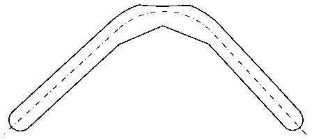
[0045] Such as Figure 5 As shown, the structure of this embodiment is basically the same as that of Embodiment 1, the difference is that: the supporting mold 11, the clamping mold 12, and the bending mold 13 are provided with semicircular grooves matching the heat pipe 50; the driving mechanism adopts a hydraulic press As a power source, the hydraulic press is connected to the link mechanism to drive the clamping die 12 and the bending die 13 to swing.

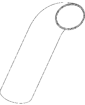
[0046]The heat pipe 50 in this embodiment adopts a round copper tube with a diameter of 6.0mm, a wall thickness of 0.30mm, and a length of 200.0mm, and the two ends of the round copper tube are closed, and the inside is vacuumized and filled with 1.0ml of pure water as the working medium . A thermocouple 41 is attached to the side of the heat pipe 50 .

[0047] The operation steps of this embodiment are as follows:

[0048] S1: if Figure 5 As shown, the grooves of the support mold 11 and the bending mold 13 are snapped t...


PUM


Abstract

The invention relates to the technical field of heat pipe radiating, in particular to a heat pipe bending method and a heat pipe bending production device. Liquid refrigerant is arranged in a heat pipe, and the heat pipe bending method includes S1 heating the heat pipe to transfer the internal liquid refrigerant into steam; and S2 bending mechanically. The heat pipe bending method is of an optimized solution on the basis of the existing bending process forming technology. During the production process of heat pipe bending, the heat pipe is heated to transfer the internal liquid refrigerant into steam, dynamic equilibrium is performed by utilizing generated steam differences and bend buckling moments, bending limit during the heat pipe bending process is increased, section shape at bending position can be prevented from generating distortion, small-radius bending is realized, and bending pass rate is increased.

Description

technical field [0001] The present invention relates to the technical field of heat dissipation, in particular to heat pipe technology, and more particularly to a heat pipe bending method and a heat pipe bending manufacturing device. Background technique [0002] With the rapid development of high-performance chip technology and the continuous improvement of electronic packaging and integration, the requirements for the cooling system of electronic components are getting higher and higher. Especially in the field of computer technology. [0003] Integrated circuits are heavily used in computer components. As we all know, high temperature is the enemy of integrated circuits. High temperature will not only lead to unstable operation of the system, shorten the service life, and may even burn some components. The heat that causes high temperature does not come from outside the computer, but from inside the computer, or inside the integrated circuit. The function of the radia...

Claims


Application Information

Patent Timeline
IPC IPC(8): B21D7/08B21D7/16
Inventor 蒋乐伦黄勇凌金田乔西凤
Owner SUN YAT SEN UNIV
Why Eureka
Try Eureka