Thermal compression bonding power source

A technology of hot-press welding and hot-press welding head, which is applied in the field of hot-press welding, can solve problems such as control errors, large fluctuations in temperature control waveforms, and temperature overshoot, and achieve the effects of improving stability and avoiding temperature overshoot

Inactive Publication Date: 2014-12-17
广州市精源电子设备有限公司 +1
View PDF8 Cites 0 Cited by
  • Summary
  • Abstract
  • Description
  • Claims
  • Application Information

AI Technical Summary

Problems solved by technology

[0013] Therefore, when the heating speed is fast, the temperature of the welding head is already very high, but the thermocouple does not respond in time. When the temperature curve changes from the rising section to the stable section, the controller obtains delayed feedback information, which makes the control error and fails to recover from the temperature in time. The heating temperature rise control is switched to the stable temperature control, resulting in temperature overshoot, see figure 1 as shown, figure 1 It is a schematic diagram of temperature overshoot, and curve 1 is the set temperature curve, and due to the phenomenon of temperature overshoot, the actual curve is shown in curve 2, from figure 1 It can be seen that the above hot-press welding power supply technology has large temperature control waveform fluctuations, poor stability and low accuracy.

Method used


Image

  • Thermal compression bonding power source
  • Thermal compression bonding power source
  • Thermal compression bonding power source

Examples


Embodiment Construction

[0031] The specific implementation of the heat-compression welding power source of the present invention will be described in detail below in conjunction with the accompanying drawings.

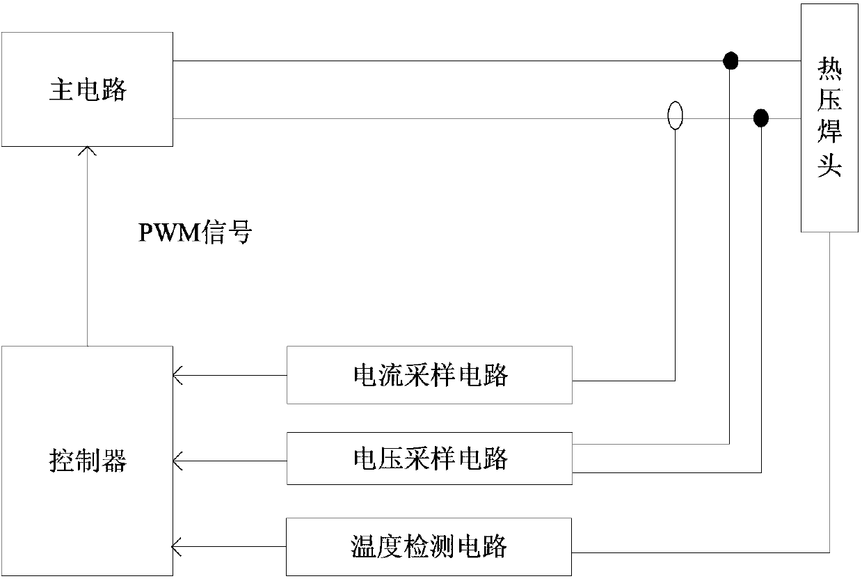
[0032] figure 2 It shows a schematic structural diagram of a thermocompression welding power source of an embodiment, including: a main circuit for outputting direct current / pulse current to a thermocompression welding head, a controller, and current sampling circuits respectively connected to the thermocompression welding heads , voltage sampling circuit and temperature detection circuit.

[0033] The main circuit adjusts the output current of the main circuit according to the PWM signal output by the controller.

[0034] The current sampling circuit collects the output current of the main circuit to obtain a feedback current value and outputs it to the controller.

[0035] The voltage sampling circuit collects the voltage at both ends of the thermocompression welding head to obtain a fee...


PUM


Abstract

A thermal compression bonding power source comprises a main circuit, a controller, a current sampling circuit, a voltage sampling circuit and a temperature detection circuit, wherein the main circuit outputs a direct current / a pulse current to a thermal compression bonding head, and the current sampling circuit, the voltage sampling circuit and the temperature detection circuit are respectively connected to the thermal compression bonding head. The main circuit adjusts the output current according to a PWM signal. The current sampling circuit collects the output current of the main circuit and obtains a feedback current value. The voltage sampling circuit collects voltages of two ends of the thermal compression bonding head and obtains a feedback voltage value. The temperature detection circuit detects the temperature of the welding position of the thermal compression bonding head and obtains a thermal electromotive force signal. The controller is used for controlling the temperature process of the thermal compression bonding head according to a preset temperature curve, obtaining a feedback temperature value according to the thermal electromotive force signal, and controlling a duty ratio of the PWM signal according to the feedback current value, the feedback voltage value and the feedback temperature value. According to the thermal compression bonding power source, identification for temperature sensing lag time is achieved, feed forward control over the temperature is conducted according to the lag time, the phenomenon of temperature overshooting caused by the temperature feedback lag is avoided, and stability of the temperature control is improved.

Description

technical field [0001] The invention relates to the technical field of thermocompression welding, in particular to a thermocompression welding power source. Background technique [0002] In recent years, in the manufacture of electronic devices, medical equipment, sensors and other products, more thin coaxial wires, soldering of PCB substrates and FPC, FFC, ACF connection of LCD and TCP, insulated enameled wires of various coil parts and Direct connection of terminals, pressure riveting of plastics, etc. [0003] At present, the welding processes used for such problems mainly include electric soldering iron soldering, reflow soldering, thermocompression welding, etc. The thermocompression welding power supply is widely used in the industry due to its following advantages: [0004] (1) It can flexibly control parameters such as temperature and time with high precision; [0005] (2) The local instantaneous heating method can well suppress the thermal influence on the surroun...

Claims


Application Information

Patent Timeline
Patent Type & Authority Patents(China)
IPC IPC(8): B23K37/00
Inventor 黄增好曹彪杨凯
Owner 广州市精源电子设备有限公司
Why Eureka
Try Eureka