Detection method of leakage site position of underground concrete continuous wall
A detection method and leakage point technology, which can be applied in infrastructure testing, construction, infrastructure engineering, etc., can solve the problems of detection blind spots and high detection costs, reduce labor costs and material costs, and improve detection rates Effect
- Summary
- Abstract
- Description
- Claims
- Application Information
AI Technical Summary
Problems solved by technology
Method used
Image

Examples
Embodiment Construction
[0038] The solution of the present invention will be described in detail below in conjunction with the accompanying drawings.
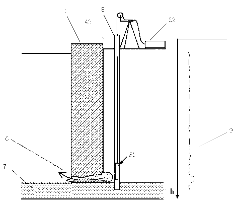
[0039] The underground concrete diaphragm wall is a concrete component. If the pouring is not dense, there will be gaps, or silt and slag inclusions. When the foundation pit is dewatered, the silt and slag inclusions form leakage under the groundwater pressure outside the foundation pit, and the silt and sand are gradually washed away by the leakage to form gaps. These voids are bound to be filled with groundwater. The dielectric constants of concrete and water are quite different, and the leakage site can be found by using the difference in the propagation speed of electromagnetic waves in media with different dielectric constants.
[0040] The speed of an electromagnetic wave in a medium:
[0041] ,
[0042] In the formula: V—the electromagnetic wave velocity in the medium; C—the electromagnetic wave velocity in the air; ε—the dielectric consta...
PUM
 Abstract
Description
Claims
Application Information
 - Generate Ideas
- Intellectual Property
- Life Sciences
- Materials
- Tech Scout
- Unparalleled Data Quality
- Higher Quality Content
- 60% Fewer Hallucinations
Browse by: Latest US Patents, China's latest patents, Technical Efficacy Thesaurus, Application Domain, Technology Topic, Popular Technical Reports.
© 2025 PatSnap. All rights reserved.Legal|Privacy policy|Modern Slavery Act Transparency Statement|Sitemap|About US| Contact US: help@patsnap.com