Piezoelectric power generation type damping-adjustable hydro-pneumatic suspension
A technology of piezoelectric power generation and oil-pneumatic suspension, which is applied in the direction of shock absorbers, shock absorbers, springs/shock absorbers, etc., and can solve the problems of low current, low energy conversion rate, and insignificant damping effect of air spring on vehicle vibration, etc. question
- Summary
- Abstract
- Description
- Claims
- Application Information
AI Technical Summary
Problems solved by technology
Method used
Image

Examples
Embodiment Construction
[0014] In order to illustrate the present invention better, in conjunction with accompanying drawing, give examples as follows:
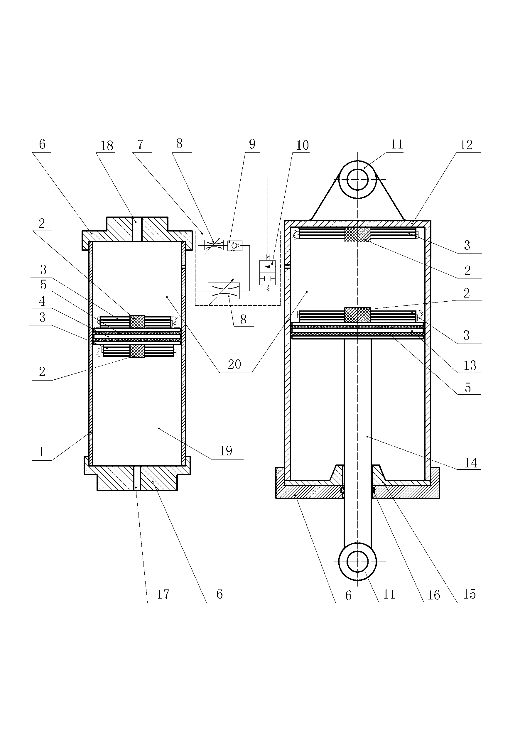
[0015] The piezoelectric generating type damping adjustable oil-pneumatic suspension of the present invention is composed of a suspension cylinder (12) and its components, an accumulator (1) and its components, and is characterized in that: the suspension cylinder (12) and the accumulator ( 1) are connected by hydraulic valve group (7); hydraulic valve group (7) is composed of electromagnetic switch valve (10), throttle valve (8) and check valve (9), among which, throttle valve (8) Connect with the one-way valve (9), and then connect with another throttle valve (8) in parallel, connect the electromagnetic switch valve (10) after the parallel connection, and connect the electromagnetic switch valve (10) with the remote control switch near the steering wheel to realize the oil-pneumatic suspension The blocking function of each throttle valve (8) in th...
PUM
 Abstract
Description
Claims
Application Information
 - R&D
- Intellectual Property
- Life Sciences
- Materials
- Tech Scout
- Unparalleled Data Quality
- Higher Quality Content
- 60% Fewer Hallucinations
Browse by: Latest US Patents, China's latest patents, Technical Efficacy Thesaurus, Application Domain, Technology Topic, Popular Technical Reports.
© 2025 PatSnap. All rights reserved.Legal|Privacy policy|Modern Slavery Act Transparency Statement|Sitemap|About US| Contact US: help@patsnap.com