Recycled constant-temperature ceramic floor integrated system

An integrated system and floor technology, applied in the field of building materials, can solve the problems of inability to erect heat pipes, poor heat source supply, and large on-site construction volume.

Inactive Publication Date: 2013-08-28
FUJIAN LOPO TERRACOTTA PANELS MFG
View PDF4 Cites 17 Cited by
  • Summary
  • Abstract
  • Description
  • Claims
  • Application Information

AI Technical Summary

Problems solved by technology

The existing floor heating usually adopts the following forms: water floor heating and electric floor heating. Water floor heating uses hot water with a temperature not higher than 60°C as the heat medium, which circulates in the heating pipes buried in the filling layer below the ground, heating For the entire floor, electric floor heating is to bury heating cables whose outer surface allowable operating temperature is 65°C in the floor, and use the heating cables as the heat source to heat the floor to achieve ground radiation heating; while the existing construction methods are complex and require on-site construction. It is large and in the process of construction and concrete solidification, it is easy to damage the above paving

Method used


Image

  • Recycled constant-temperature ceramic floor integrated system
  • Recycled constant-temperature ceramic floor integrated system
  • Recycled constant-temperature ceramic floor integrated system

Examples


Embodiment Construction

[0022] The present invention will be further described below in conjunction with the accompanying drawings and specific embodiments.

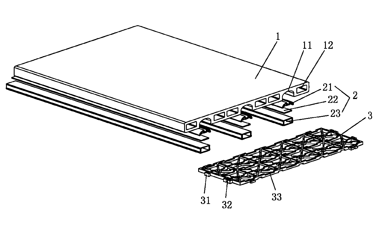
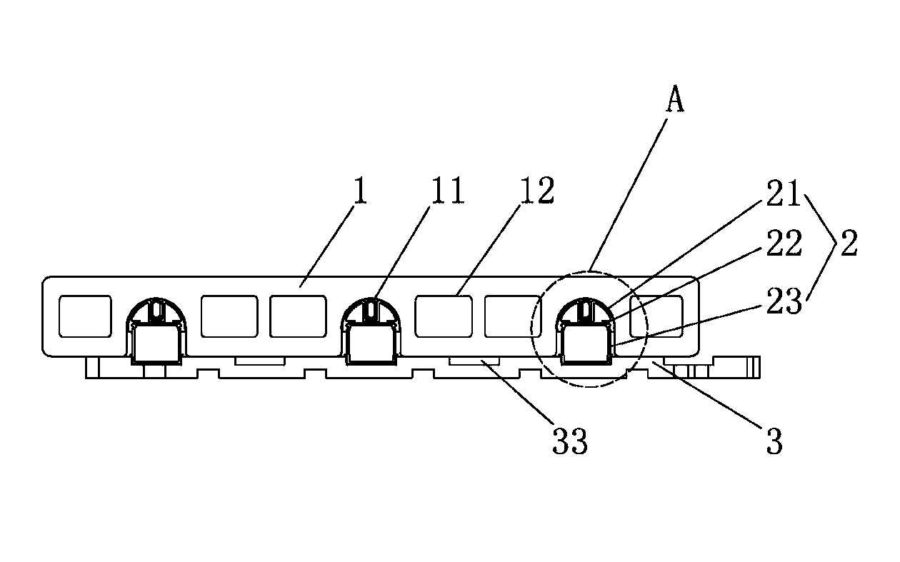
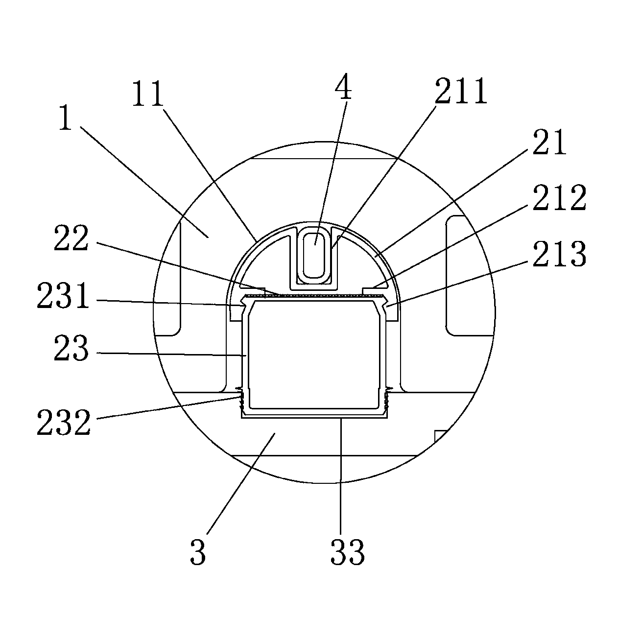
[0023] Such as figure 1 , figure 2 As shown, this embodiment 1 adopts the floor integrated system of the electric heating device, including the floor tile 1, and there are several grooves 11 arranged in parallel at intervals on the bottom surface of the floor tile 1, and the cross-sectional shape of the groove 11 is "U" shape The middle part of the floor tile 1 is also provided with several square hollow holes 12, which effectively reduce the weight and save the use of materials. The bottom surface of the floor tile 1 is connected with a substrate 3, and all lay There is a bracket assembly 2, and the bracket assembly 2 includes a heat conduction element 21 and a positioning bracket 23 that are built up and down. A reflective film 22 is provided between the heat-conducting member 21 and the positioning bracket 23. The reflective film 22 can b...


PUM


Abstract

The invention relates to the field of building materials, in particular to a recycled constant-temperature ceramic floor integrated system. The recycled constant-temperature ceramic floor integrated system comprises floor tiles, wherein a plurality of grooves are formed in the bottom surfaces of the floor tiles. The bottom surfaces of the floor tiles are connected with base plates, support assemblies are arranged among the grooves and the base plates in a laid mode and comprise heat-conducting pieces and locating supports which are installed in an up-and-down lapping mode, reflecting films are arranged among the heat-conducting pieces and the locating supports, the base plates are made of plate pieces of a net structure, and hasp grooves and hasp blocks are arranged on the peripheries of the base plates. According to the recycled constant-temperature ceramic floor integrated system, the structure is arranged in a modular split joint mode, the support assemblies are arranged among the floor tiles and the base plates in a laid mode, the support assemblies needed by water heating or electric heating can be correspondingly arranged combining with requirements for specific using conditions, the structure is tight and firm after the support assemblies are assembled, sliding, displacement and slipping are not prone to occurring, the whole operation, adjustment and installing are conveniently conducted, replacement of different floor heating modes is achieved, the problem that the structure can only be laid in a single floor heating mode is completely solved, laying is economical, the floor tiles can be recovered and recycled, and universality of products is high.

Description

technical field [0001] The invention relates to the field of building materials, in particular to a recycled constant temperature ceramic floor integrated system. Background technique [0002] At present, with the development of indoor heating facilities, more and more people use floor heating. Floor heating is the abbreviation of floor radiant heating. The law of the ground's own heat storage and upward radiation conducts from bottom to top to achieve the purpose of heating. The existing floor heating usually adopts the following forms: water floor heating and electric floor heating. Water floor heating uses hot water with a temperature not higher than 60°C as the heat medium, which circulates in the heating pipes buried in the filling layer below the ground, heating For the entire floor, electric floor heating is to bury heating cables whose outer surface allowable operating temperature is 65°C in the floor, and use the heating cables as the heat source to heat the floor ...

Claims


Application Information

Patent Timeline
IPC IPC(8): F24D13/02E04F15/02
CPCE04F2015/02116E04F15/08E04F15/185E04F2290/023F24D3/14F24D13/022F24D3/142Y02B30/00E04C2/525E04F15/02
Inventor 彭幸华张谋森吴进艺
Owner FUJIAN LOPO TERRACOTTA PANELS MFG
Why Eureka
Try Eureka