Eureka AIR delivers breakthrough ideas for toughest innovation challenges, trusted by R&D personnel around the world.

Control method for multi-energy convergence coordinated control system

A technology for coordinating control systems and control methods, applied in photovoltaic power generation, electric vehicles, electrical components, etc., can solve problems such as high equipment cost, complex control, single energy source, etc., achieve the effect of reducing operating costs and realizing uninterrupted power supply

Inactive Publication Date: 2015-05-13
常州新慧能电力服务有限公司
View PDF3 Cites 0 Cited by
  • Summary
  • Abstract
  • Description
  • Claims
  • Application Information

AI Technical Summary

Problems solved by technology

Since there are many energy sources in the micro-grid and their characteristics are different, the coordinated management of energy is very important. The coordinated management of energy is not only related to the utilization rate of renewable energy, but also related to the stability of the micro-grid. Currently, in the DC micro-grid Most of them use the method of coordinating various energy sources to maintain a fixed DC bus voltage, the control is more complicated, and the equipment cost is relatively high, while the energy supporting the inverter in the AC microgrid is relatively simple, and the method of fixing the DC bus voltage is also used to control The incoming power supply is managed

Method used


Image

  • Control method for multi-energy convergence coordinated control system
  • Control method for multi-energy convergence coordinated control system

Examples


Embodiment Construction

[0020] In order to make the content of the present invention more clearly understood, the present invention will be further described in detail below based on specific embodiments and in conjunction with the accompanying drawings.

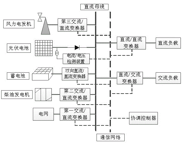
[0021] like figure 1As shown, a multi-energy confluence coordinated control system, which includes a DC bus, a first AC / DC converter, a second AC / DC converter, a bidirectional DC / DC converter, a third AC / DC converter, a coordinated control device, current / voltage detection device, DC / DC converter that can be connected to an external DC load, and a DC / AC converter that can be connected to an external AC load; The data information generates corresponding voltage control signals and transmits them to the corresponding first AC / DC converter, second AC / DC converter, bidirectional DC / DC converter, third AC / DC converter, and DC / DC converter and a DC / AC converter; the first AC / DC converter is electrically connected between the grid and the DC bus, and is ...


PUM


Abstract

The invention discloses a system and method for multi-energy convergence coordinated control. The system for multi-energy convergence coordinated control comprises a direct current bus, a first alternating current / direct current converter, a second alternating current / direct current converter, a bi-directional direct current / direct current converter, a third alternating current / direct current converter, a coordinating controller, a current / voltage detection device, a direct current / direct current converter capable of being externally connected with a direct-current load, and a direct current / alternating current converter capable of being externally connected with an alternating current load, wherein the coordinating controller can be used for receiving data information transmitted by the current / voltage detection device to generate corresponding voltage control signals and transmits the signals respectively to the corresponding first alternating current / direct current converter, the second alternating current / direct current converter, the bi-directional direct current / direct current converter, the third alternating current / direct current converter, the direct current / direct current converter and the direct current / alternating current converter. The system and method for multi-energy convergence coordinated control can carry out convergence control on input multiple paths of alternating current / direct current power supplies, coordinates voltage conversion modules of the power supplies by utilizing the coordinating controller, adjusts the voltage method of the direct current bus, tracks the maximum power point of a photovoltaic array, and lowers operating cost.

Description

technical field [0001] The invention relates to a multi-energy confluence coordinated control system and a control method thereof, which belong to the field of power electronics and automatic control, and can be applied to optimize management of various energy sources in a DC microgrid and support energy in an inverter in an AC microgrid Optimize management. Background technique [0002] At present, with the gradual depletion of conventional energy and the increasing environmental pollution, countries around the world are strengthening the development and utilization of clean and efficient renewable energy to solve energy problems in future social and economic development. Microgrids are distributed electricity (including renewable energy) ) grid connection provides an important form of network organization. At present, microgrids can be divided into DC microgrids and AC microgrids according to the form of power transmission. Microgrids are essentially a small power system i...

Claims


Application Information

Patent Timeline
Patent Type & Authority Patents(China)
IPC IPC(8): H02J7/35
CPCY02E10/56
Inventor 沈金荣陈星莺宋加才余昆鲁赫马宏辉
Owner 常州新慧能电力服务有限公司
Why Eureka
Eureka Blog
Learn More