Magnetic levitation planetary transmission speed control machine

A technology of planetary transmission and speed changer, which is applied in electromechanical transmission devices, electromechanical devices, electric components, etc., can solve the problems of small torque and low resource utilization, and achieve the effects of large transmission torque, long machine life and pollution prevention

Inactive Publication Date: 2013-08-28
苏大卫 +1
View PDF3 Cites 4 Cited by
  • Summary
  • Abstract
  • Description
  • Claims
  • Application Information

AI Technical Summary

Problems solved by technology

Its disadvantages are: the single-stage magnetic coupling is adopted, and the transmitted torque is small; the permanent magnet is arranged in a circular cylinder, and the resource utilization rate is low

Method used


Image

  • Magnetic levitation planetary transmission speed control machine
  • Magnetic levitation planetary transmission speed control machine
  • Magnetic levitation planetary transmission speed control machine

Examples


Embodiment 1

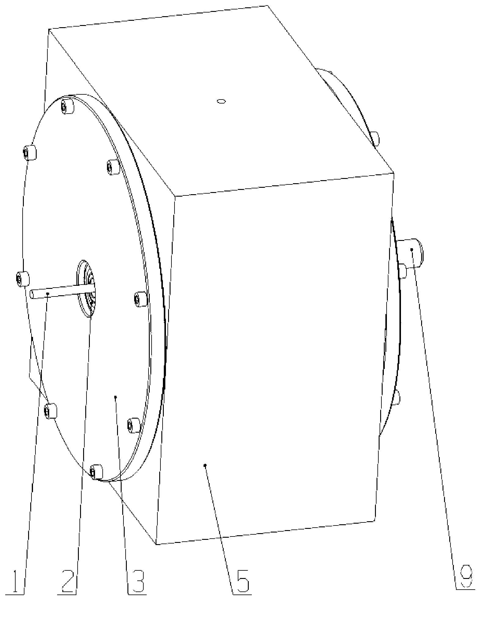
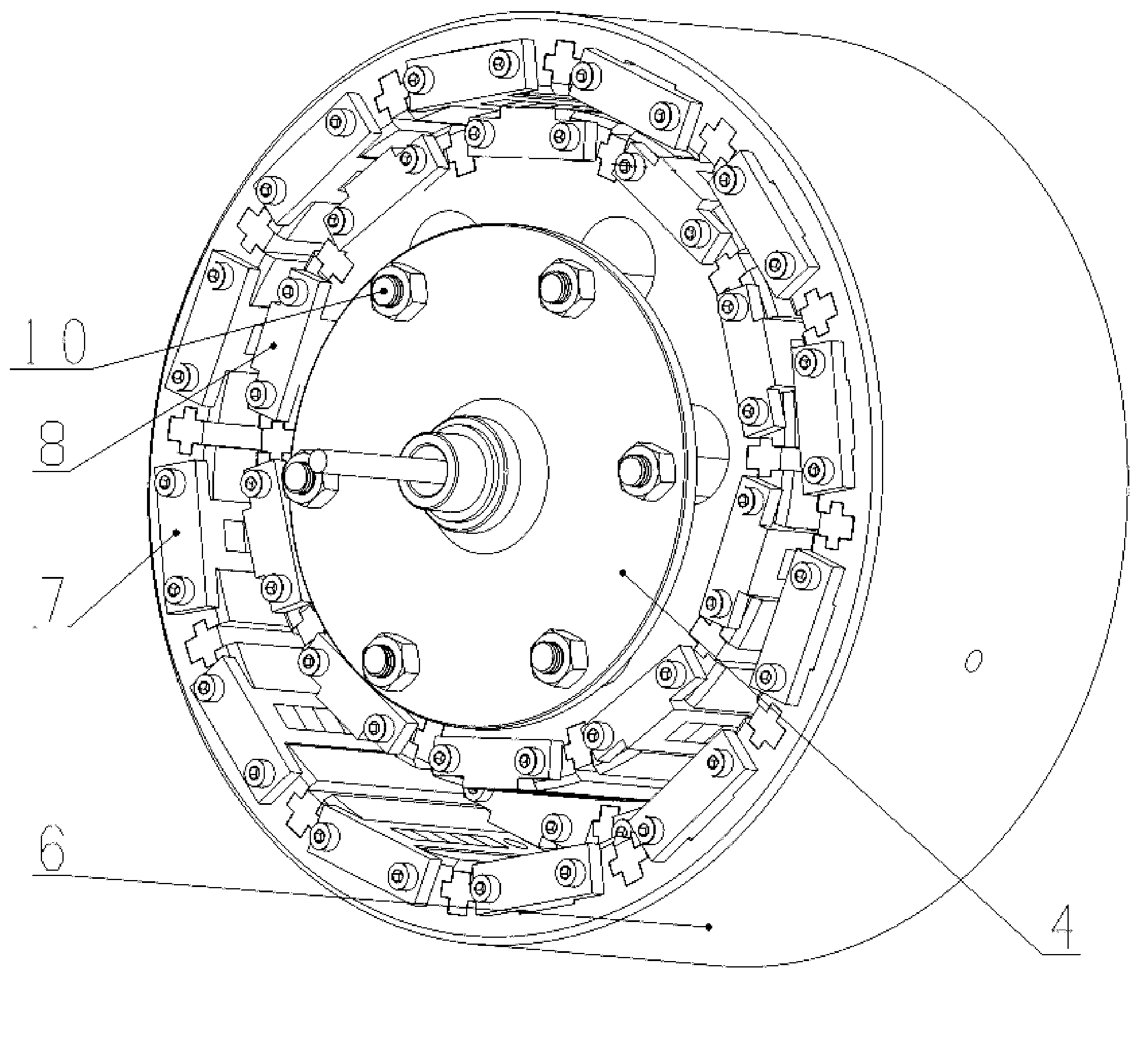
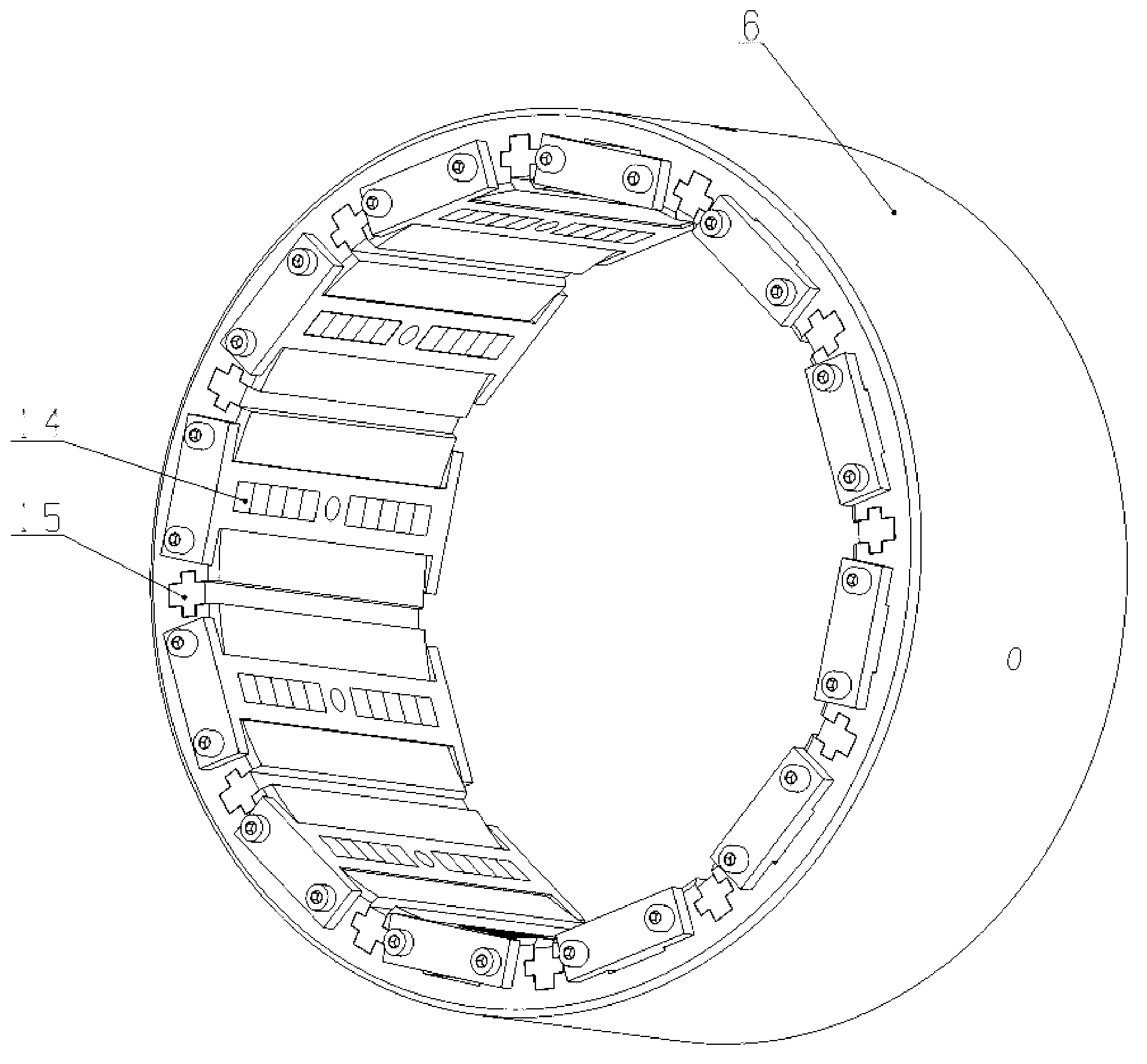
[0032] As shown in the figure, a magnetic levitation planetary transmission speed changer includes an I shaft 1, a housing 5, an II shaft 9, and a permanent magnet 14. The inner side of the housing 5 is provided with an inner ring gear 6, and the inner ring gear 6 is provided with straight grooves, the number is 12, and permanent magnet mounting frame I7 is arranged in the straight grooves, and end caps 3 are provided at both ends of the housing 5, and the center of the end caps 3 at one end of the housing 5 is connected to the input through the bearing 2 The connecting shaft 4, the center of the end cover 3 at the other end is connected to the II shaft 9 through the bearing 2, one end of the I shaft 1 is installed at the center of the input connecting shaft 4, and the other end is installed at the center of the II shaft 9, and the I shaft 1 is equipped with an eccentric shaft 11 through a key, and the eccentric shaft 11 is connected to the planetary wheel 13 through a bearing....

Embodiment 2

[0035] The difference from Embodiment 1 is that the permanent magnets 14 on the permanent magnet mounting frame I7 and the permanent magnet mounting frame II8 are arranged in a Halbach manner, and the magnetism is mutual repulsion.

[0036] This embodiment can accomplish greater torque transmission than Implementation 2.

Embodiment 3

[0038] The difference from Embodiment 1 or 2 is that the pitch of the straight grooves of the ring gear 6 is equidistant, and the number is three, and the pitch of the straight grooves on the planetary gear 13 is equidistant, and the number is two.


PUM


Abstract

The invention discloses a magnetic levitation planetary transmission speed control machine, and aims at providing a magnetic levitation planetary transmission speed control machine which is large in transmission torque, high in magnetic utilization rate, environment-friendly and pollution-free, is provided with an overload protection function and based on a Halbach-type permanent magnetic array. The magnetic levitation planetary transmission speed control machine comprises a shaft I, a shell, a shaft II and a permanent magnet, wherein an inner gear ring is arranged in the shell, the inner gear ring is provided with a permanent magnet installation frame I, two ends of the shell are respectively provided with an end cover, the center of the end cover on one end of the shell is connected with an input connecting shaft through a bearing, the center of the end cover on the other end of the shell is connected with the shaft II through a bearing, one end of the shaft I is installed in the center of the input connection shaft, the other end of the shaft I is installed in the center of the shaft II, the shaft I is provided with an eccentric shaft through a key, the eccentric shaft is connected with a planetary wheel through a bearing, and the planetary wheel is provided with a permanent magnet installation frame II. The magnetic levitation planetary transmission speed control machine not only can be used for reduction application, but also can be used for the acceleration application, and particularly applicable to the pollution-free food production line, the aviation field and the wind power generation field.

Description

technical field [0001] The invention relates to a planetary transmission speed reducer, in particular to a magnetic levitation planetary transmission speed changer. Background technique [0002] The traditional gear transmission mechanism mainly relies on the meshing force of mechanical gears to realize the transmission of torque and speed. At the moment of its transmission, only two teeth contact to do work, which will cause wear, noise, vibration, and other teeth do not do work. The utilization rate is low, and at the same time, in order to ensure the operation of the system, lubricating oil needs to be added for lubrication and cooling, which is easy to pollute the environment. Therefore, traditional gear drives cannot be used in some special environments, such as food manufacturing, aerospace and other fields. [0003] In order to solve the shortcomings of traditional gear transmission, inventors in the last century have proposed magnetic levitation transmission using e...

Claims


Application Information

Patent Timeline
Patent Type & Authority Applications(China)
IPC IPC(8): H02K51/00
Inventor 苏大卫吴洁玲
Owner 苏大卫
Why Eureka
Try Eureka