Large-scale fluidization storehouse
A fluidization and storage technology, applied in the field of floor storage, can solve problems such as casualties, economic losses, and difficulty in inspection, and achieve the effects of less supporting facilities, less maintenance work, and less difficulty in loading materials.
- Summary
- Abstract
- Description
- Claims
- Application Information
AI Technical Summary
Problems solved by technology
Method used
Image
Examples
Embodiment 1
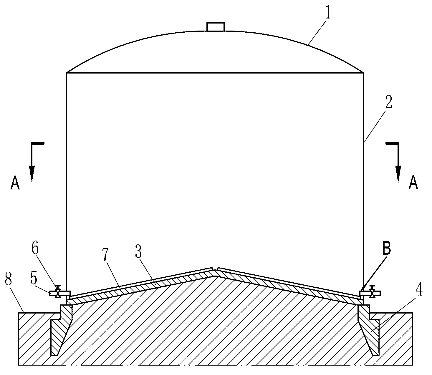
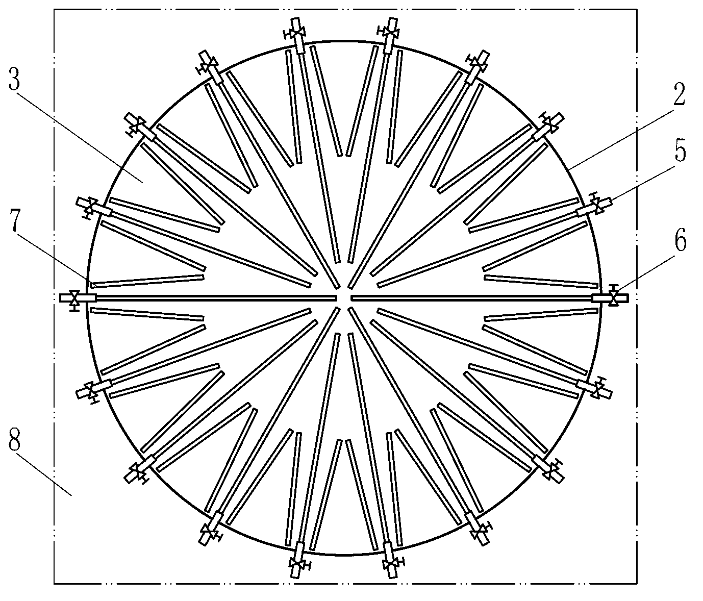
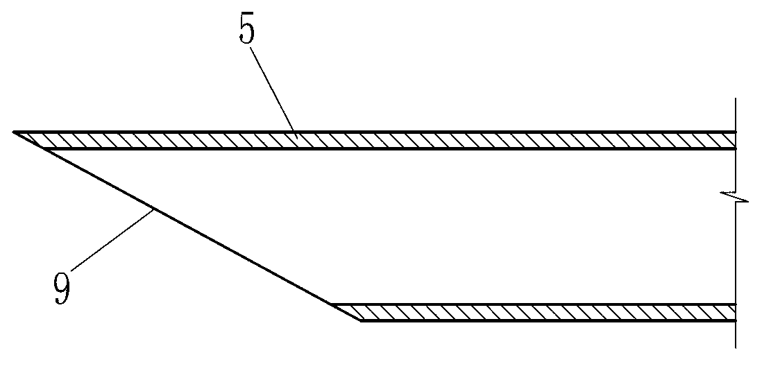
[0028] Such as figure 1 , figure 2 and image 3 The shown large-scale fluidized storage of the present invention comprises a top 1, a wall 2, a bottom 3 and a foundation 4. The top 1, the wall 2, the bottom 3 and the foundation 4 are all made of reinforced concrete. Most of the foundation 4 is buried in the land 8, and the bottom 3 of the reservoir is integrated with the foundation 4 of the reservoir. Wherein, library bottom 3 comprises a conical arch, and the highest point of cone arch is located at the center of the library bottom or near the center of the library bottom, and the slope of the cone arch extends to the bottom of the library wall 2. The lower part of the arched cone is filled with earth and tamped, and waterproofed; the inclined surface of the arched cone is provided with a material flow aid device 7, which is composed of vibrating rods, and a group of three vibrating rods is evenly arranged at the bottom of the reservoir 3 surface; the bottom of the wareho...
Embodiment 2
[0039] Such as Figure 4 , Figure 5 , Figure 6 and Figure 7 The difference between the large fluidized storage of the present invention and the first embodiment is that the roof 1, the wall 2 and the bottom 3 are made of steel plates, and the wall 2 and the bottom 3 are welded together. The material flow aid device 7 adopts a pneumatic fluidization rod, and correspondingly adds an air supply pipeline for the pneumatic fluidization rod. The air supply pipeline includes an air supply main pipe 10 arranged outside the warehouse wall 2, and the air supply main pipe 10 is arranged around the warehouse wall 2. It is also connected to air supply devices such as air compressors or air tanks (conventional equipment, not specifically shown in the figure), and the main gas supply pipe 10 communicates with the pneumatic fluidization rod through the air supply branch pipe 11. There is a valve 26 for controlling air volume and pressure. In order to facilitate discharging, the arched ...
Embodiment 3
[0042] In order to facilitate the removal of powdery materials through the discharge channel, such as Figure 8 and Figure 9 The difference between the large-scale fluidized storage of the present invention shown in Embodiment 2 is that the discharge passage 5 includes a material conveying pipe 15, and the material conveying pipe 15 extends to the middle part of the bottom 3 of the storehouse along the inclined surface of the cone arch, and the material conveying A plurality of blanking ports 19 are arranged on the pipe 15, surroundings 20 are provided around the blanking port 19, and a pneumatic fluidizing rod 16 is also arranged in the material conveying pipe 15, and the pneumatic fluidizing rod 16 is located in the lumen of the material conveying pipe 15 At the bottom, the conical arch is provided with an air supply pipeline 13, and one end of the material conveying pipe 15 positioned at the inside of the storehouse wall is connected to the feed blowing pipe 17 in the air ...
PUM
 Abstract
Description
Claims
Application Information
 - R&D
- Intellectual Property
- Life Sciences
- Materials
- Tech Scout
- Unparalleled Data Quality
- Higher Quality Content
- 60% Fewer Hallucinations
Browse by: Latest US Patents, China's latest patents, Technical Efficacy Thesaurus, Application Domain, Technology Topic, Popular Technical Reports.
© 2025 PatSnap. All rights reserved.Legal|Privacy policy|Modern Slavery Act Transparency Statement|Sitemap|About US| Contact US: help@patsnap.com


