large fluidized storage

A fluidization and storage technology, applied in the field of floor storage, can solve the problems of difficult inspection, hidden dangers, casualties, etc., and achieve the effect of less difficulty in feeding materials, convenient maintenance, and fewer supporting facilities.

Active Publication Date: 2016-01-20
赵世青
View PDF6 Cites 0 Cited by
  • Summary
  • Abstract
  • Description
  • Claims
  • Application Information

AI Technical Summary

Problems solved by technology

However, the discharge ports of the existing large-scale fluidized storage are all set in the discharge corridor, which is not easy to check. Once the flow control device is damaged, it will be difficult to block the large flow of materials in the storage, and it is easy to block and bury the discharge corridor. Material conveying equipment, causing great economic losses, especially when there are people in the unloading corridor, may also cause casualties, so there are certain safety hazards

Method used


Image

  • large fluidized storage
  • large fluidized storage
  • large fluidized storage

Examples


Embodiment 1

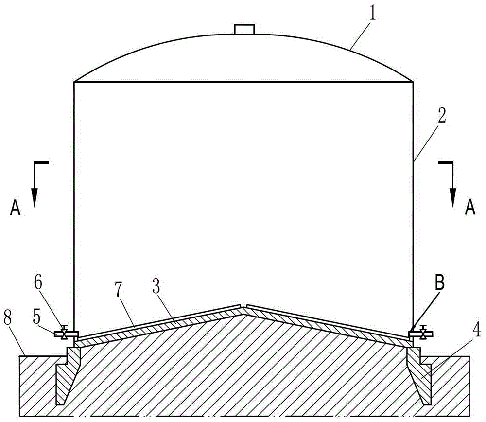
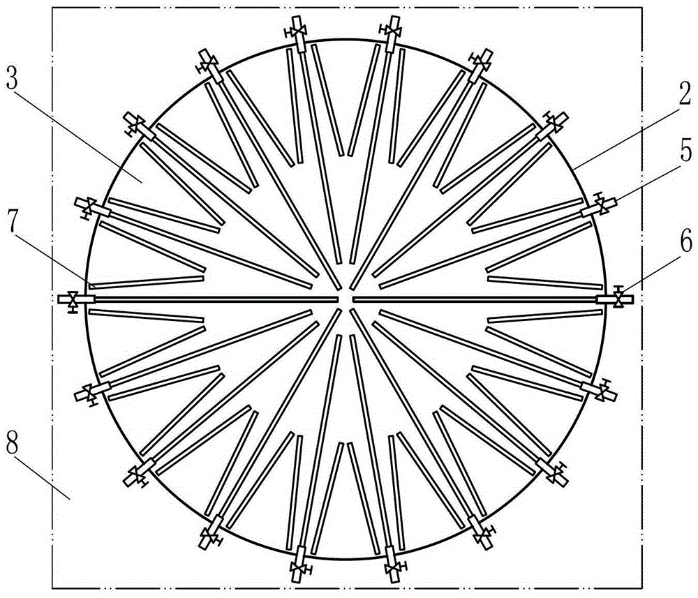
[0028] Such as figure 1 , figure 2 and image 3 The shown large-scale fluidized storage of the present invention comprises a top 1, a wall 2, a bottom 3 and a foundation 4. The top 1, the wall 2, the bottom 3 and the foundation 4 are all made of reinforced concrete. Most of the foundation 4 is buried in the land 8, and the bottom 3 of the reservoir is integrated with the foundation 4 of the reservoir. Wherein, library bottom 3 comprises a conical arch, and the highest point of cone arch is located at the center of the library bottom or near the center of the library bottom, and the slope of the cone arch extends to the bottom of the library wall 2. The lower part of the arched cone is filled with earth and tamped, and waterproofed; the inclined surface of the arched cone is provided with a material flow aid device 7, which is composed of vibrating rods, and a group of three vibrating rods is evenly arranged at the bottom of the reservoir 3 surface; the bottom of the wareho...

Embodiment 2

[0039] Such as Figure 4 , Figure 5 , Figure 6 and Figure 7 The difference between the large fluidized storage of the present invention and the first embodiment is that the roof 1, the wall 2 and the bottom 3 are made of steel plates, and the wall 2 and the bottom 3 are welded together. The material flow aid device 7 adopts a pneumatic fluidization rod, and correspondingly adds an air supply pipeline for the pneumatic fluidization rod. The air supply pipeline includes an air supply main pipe 10 arranged outside the warehouse wall 2, and the air supply main pipe 10 is arranged around the warehouse wall 2. It is also connected to air supply devices such as air compressors or air tanks (conventional equipment, not specifically shown in the figure), and the main gas supply pipe 10 communicates with the pneumatic fluidization rod through the air supply branch pipe 11. There is a valve 26 for controlling air volume and pressure. In order to facilitate discharging, the arched ...

Embodiment 3

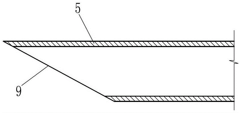
[0042] In order to facilitate the removal of powdery materials through the discharge channel, such as Figure 8 and Figure 9 The difference between the large-scale fluidized storage of the present invention shown in Embodiment 2 is that the discharge passage 5 includes a material conveying pipe 15, and the material conveying pipe 15 extends to the middle part of the bottom 3 of the storehouse along the inclined surface of the cone arch, and the material conveying A plurality of blanking ports 19 are arranged on the pipe 15, surroundings 20 are provided around the blanking port 19, and a pneumatic fluidizing rod 16 is also arranged in the material conveying pipe 15, and the pneumatic fluidizing rod 16 is located in the lumen of the material conveying pipe 15 At the bottom, the conical arch is provided with an air supply pipeline 13, and one end of the material conveying pipe 15 positioned at the inside of the storehouse wall is connected to the feed blowing pipe 17 in the air ...


PUM


Abstract

The invention relates to a large-scale fluidization storehouse. The large-scale fluidization storehouse comprises a storehouse top, a storehouse wall, a storehouse bottom and a storehouse foundation. The large-scale fluidization storehouse is characterized in that the storehouse bottom comprises a conical arch, the highest point of the conical arch is located at the center of the storehouse bottom or near the center of the storehouse bottom, the inclined plane of the conical arch extends to the bottom of the storehouse wall, a material flow-assisting device is arranged on the inclined plane of the conical arch, a discharging channel is disposed at the bottom of the storehouse wall, a feeding end of the discharging channel extends nearby the material flow-assisting device arranged on the inclined plane of the conical arch in the storehouse wall, and a discharging end of the discharging channel, which is positioned on the outer side of the storehouse wall, is provided with a channel flow control device. The large-scale fluidization storehouse has the advantages of being simple in structure, small in investment, large in storage capacity, short in construction cycle, low in construction difficulty, easy to maintain, small in occupies area, superior in economy and safety, capable of being widely applied to storage of powdery or granular materials such as fly ash, cement and grain and the like.

Description

technical field [0001] The invention relates to the field of storage equipment, in particular to a floor storage for storing powdery or granular materials. Background technique [0002] At present, floor-standing large-scale fluidized storages are mainly divided into two types: concrete silos and steel plate silos. The silo is cylindrical in shape and has the characteristics of large storage capacity and good stability. It is widely used in building materials, grain and chemical raw materials, etc. Storage of powdery or granular materials. Existing large-scale fluidized storage mainly relies on the discharge port at the bottom of the storage to discharge materials, and the corresponding discharge corridor is set at the bottom of the storage to lead to the outside of the storage to accommodate material conveying equipment and provide maintenance space. In order to ensure the rate of material out of the warehouse, it is usually necessary to set up multiple discharge ports, an...

Claims


Application Information

Patent Timeline
Patent Type & Authority Patents(China)
IPC IPC(8): B65D88/72
Inventor 赵世青
Owner 赵世青
Why Eureka
Try Eureka