Global navigation satellite signal reflectometry (GNSS-R) detection equipment for sea ice thickness and method for detecting sea ice thickness by utilizing equipment

A technology for detection equipment and seawater, applied in the direction of electric/magnetic thickness measurement, electromagnetic measurement devices, etc., can solve the problems of no clear description of the detection of sea ice thickness, discontinuous monitoring data in time and space, poor current potential, etc., and achieve light weight and low cost , reliable results

Inactive Publication Date: 2013-09-04
柯福阳
View PDF6 Cites 19 Cited by
  • Summary
  • Abstract
  • Description
  • Claims
  • Application Information

AI Technical Summary

Problems solved by technology

[0008] Moreover, the above-mentioned sea ice thickness monitoring technologies all have a common defect: the monitoring data is discontinuous in time and space, poor in current situation, low in efficiency, and low in accuracy.
However, there are no relevant literature reports on the experimental research in this area in our country.
Although the utility model patent "A Sea Ice Microwave Remote Sensing Monitoring System" (CN201754185U) mentions the use of GNSS-R to monitor sea ice, it is used in combination with RADARSAT (radar) and other equipment, and it is not clearly stated that it is used to detect sea ice. Ice thickness, and a corresponding rationale for sea ice monitoring given

Method used


Image

  • Global navigation satellite signal reflectometry (GNSS-R) detection equipment for sea ice thickness and method for detecting sea ice thickness by utilizing equipment
  • Global navigation satellite signal reflectometry (GNSS-R) detection equipment for sea ice thickness and method for detecting sea ice thickness by utilizing equipment
  • Global navigation satellite signal reflectometry (GNSS-R) detection equipment for sea ice thickness and method for detecting sea ice thickness by utilizing equipment

Examples


Embodiment Construction

[0024] Below in conjunction with accompanying drawing, the technical scheme of invention is described in detail:

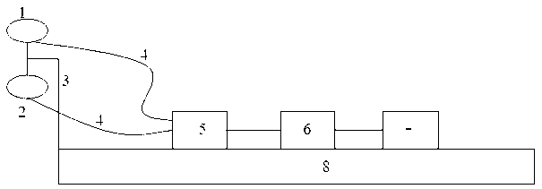
[0025] GNSS-R sea ice thickness detection equipment such as figure 1 As shown, it includes: a GNSS right-hand polarized antenna 1 and a GNSS left-hand polarized antenna 2 erected on the antenna bracket 3, a GNSS-R receiver 5 placed on an operating platform 8, an industrial computer 6, and a display 7. The GNSS-R receiver 5 includes sequentially connected amplifiers, filters, radio frequency front-ends, and signal correlators. GNSS right-handed polarized antenna 1 and GNSS left-handed polarized antenna 2 are respectively connected to the input end of GNSS-R receiver 5 through GNSS signal transmission feeder 4, the input end of industrial computer 6 is connected to the output end of GNSS-R receiver 5, and the display 7 is connected to Industrial computer 6 output. GNSS right-handed polarized antenna 1 is used to receive GNSS direct signals; GNSS left-handed polari...


PUM


Abstract

The invention discloses global navigation satellite signal reflectometry (GNSS-R) detection equipment for sea ice thickness and a method for detecting the sea ice thickness by utilizing the equipment and belongs to the technical field of ocean monitoring. The detection equipment comprises a GNSS right-handed rotation polarizing antenna, a GNSS left-handed rotation polarizing antenna, a GNSS-R receiver, an industrial computer and a displayer, wherein the GNSS right-handed rotation polarizing antenna and the GNSS left-handed rotation polarizing antenna are erected on an antenna stand; and the GNSS-R receiver, the industrial computer and the displayer are arranged on an operating platform. According to the method, sea ice radiance is obtained by computing GNSS direct power and reflection power, and then, inversion is performed according to a function relationship between the radiance and the sea ice thickness to obtain the sea ice thickness. The detection equipment is small in size, light in weight and low in cost, is convenient to carry and is flexibly used and simply operated in region and airspace. The detection method has the advantages that the sea ice thickness is detected in real time, the precision is high, results are reliable, and the up-to-date performance is powerful.

Description

technical field [0001] The invention discloses GNSS-R sea ice thickness detection equipment and a method for detecting sea ice thickness by using the equipment, belonging to the technical field of marine monitoring. Background technique [0002] Sea ice is one of the most important disasters in nature, which has a major impact on maritime transportation, marine resource development, and global climate change. my country is one of the countries most seriously endangered by sea ice in the world. In 2010, my country's Bohai Rim region encountered the most serious sea ice disaster in the past 30 years, and the direct economic loss due to the disaster was as high as 6.318 billion yuan, accounting for 47.6% of the total economic loss of marine disasters throughout the year. With the impact of global climate change, the frequency of sea ice disasters is also increasing. In 2011 and 2012, serious sea ice disasters occurred in the Bohai Rim. Therefore, timely, rapid and accurate mo...

Claims


Application Information

Patent Timeline
Patent Type & Authority Applications(China)
IPC IPC(8): G01B7/06
Inventor 柯福阳
Owner 柯福阳
Why Eureka
Try Eureka