
Device and method for gas bearing shale-seepage-temperature coupling and displacement experiment

A stress and shale technology, applied in the field of gas-bearing shale stress-seepage-temperature coupling and displacement test devices, can solve the problem that the displacement experiment cannot reveal the displacement law of gas-bearing shale, the study of the displacement effect, the deformation and penetration performance cannot be recorded and analyzed synchronously

Active Publication Date: 2013-09-04
NORTHEASTERN UNIV
View PDF7 Cites 57 Cited by
  • Summary
  • Abstract
  • Description
  • Claims
  • Application Information

AI Technical Summary

Problems solved by technology

[0007] The current experiments and devices for testing the deformation and permeability of tight gas-bearing shale have the following problems: the shale deformation and permeability experiments are carried out separately, so that the deformation and permeability cannot be recorded and analyzed simultaneously, and cannot reflect the actual mining process. Dynamic Coupling Change Process of Rock Deformation and Permeability
However, the current displacement experimental equipment has the following problems: the displacement experiment cannot be carried out in a triaxial stress environment, and the gas-bearing shale reservoirs are mostly buried below a thousand meters in a high-stress environment. Displacement experiments in triaxial stress environment cannot reveal the actual displacement law of gas-bearing shale
Moreover, in the current displacement experiments, the injected mixed displacement gas is injected at isobaric pressure, and the study of the displacement effect of the fixed ratio and isobaric mixed gas has not been realized.

Method used


Image

  • Device and method for gas bearing shale-seepage-temperature coupling and displacement experiment
  • Device and method for gas bearing shale-seepage-temperature coupling and displacement experiment

Examples


Embodiment Construction

[0049] The present invention will be further described below in conjunction with embodiment.

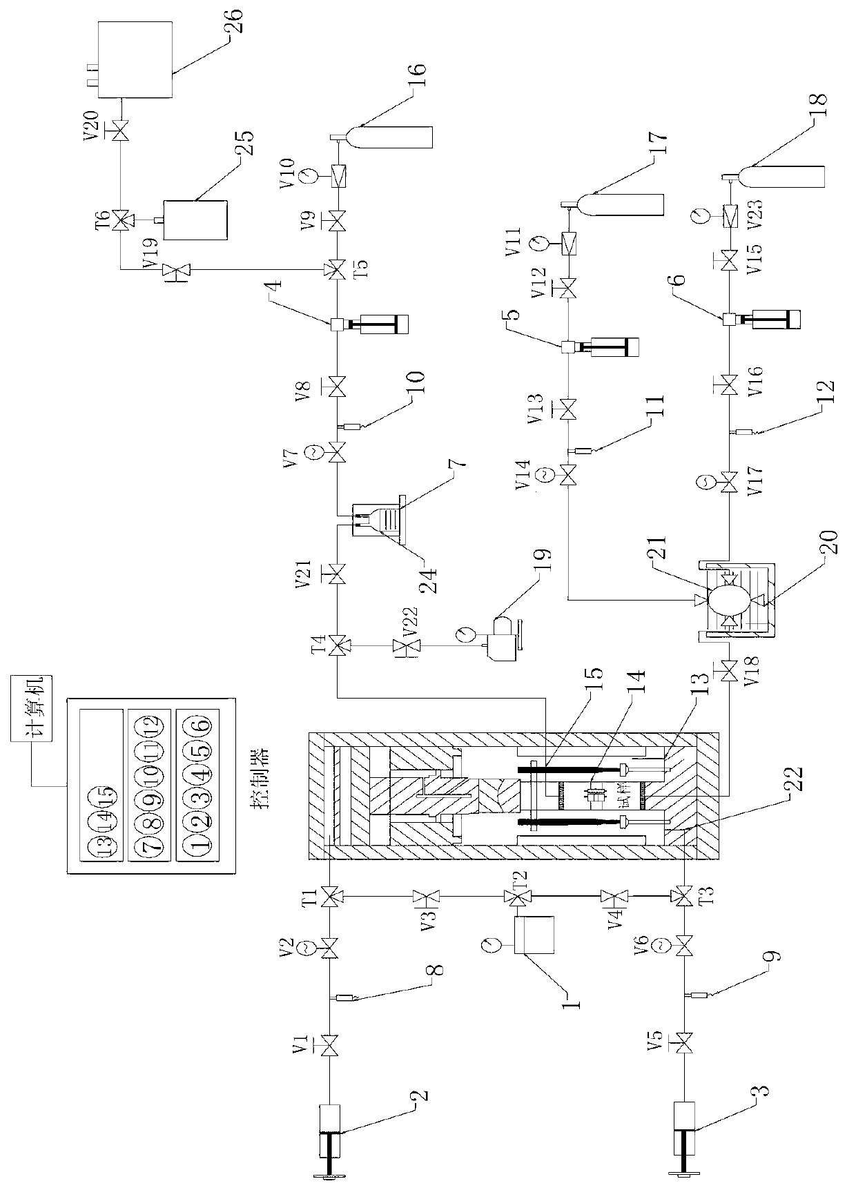
[0050] The gas-bearing shale stress-seepage-temperature coupling and displacement test device of the present invention includes a triaxial pressure chamber, an axial pressure loading system, a confining pressure loading system, an upstream gas pressure loading system, an upstream liquid pressure loading system, a downstream Gas-liquid mixed fluid collection system, multi-component mixed gas collection system, vacuum device, heating system and data acquisition and control system; where:

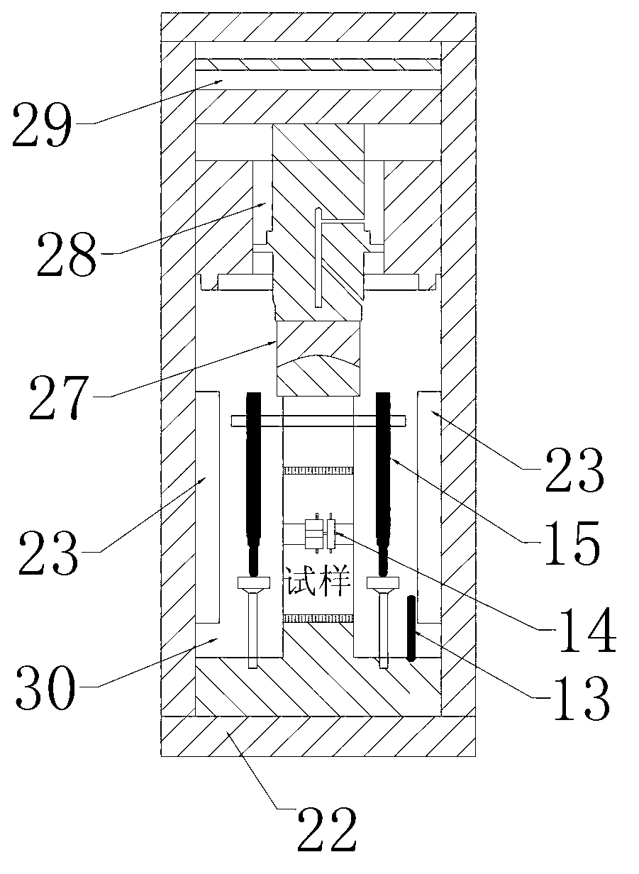
[0051] The triaxial pressure chamber 22 includes an axial pressure chamber 29, a confining pressure chamber 30, a self-balancing piston 28, a ball head 27, a spring type axial displacement sensor 15, a chain type circumferential displacement sensor 14, a temperature sensor 13 and Heating device 23;

[0052] The axial pressure loading system includes an oil pump 1, an axial pressure pump 2, a first c...


PUM


Abstract

The invention belongs to the field of rock engineering, and in particular relates to a device and a method for a gas bearing shale-seepage-temperature coupling and displacement experiment. The experimental device comprises a triaxial pressure cavity, an axial pressure loading system, a confining pressure loading system, an upstream gas pressure loading system, an upstream liquid pressure loading system, a downstream gas pressure loading and collecting system, a downstream liquid collecting system, a multi-component mixed gas collecting system, a vacuumizing device, a heating system and a data collection control system. The experimental method comprises the following steps of: fixing a test piece; applying confining pressure; applying axial pressure; heating; vacuumizing; applying upstream liquid pressure (or pre-saturated methane); applying upstream gas pressure (or applying upstream gas pressure); injecting multi-phase mixed fluid (or applying another upstream liquid pressure); performing pre-adsorptive saturation by the test piece (injecting multi-component constant-proportion mixed gas); and collecting. The experimental device can be used for applying triaxial stress to the test piece according to the actual stress condition, and remolding a stress environment according to the fact.

Description

[0001] technical field [0002] The invention belongs to the field of rock engineering, in particular to a device and method for gas-bearing shale stress-seepage-temperature coupling and displacement test. Background technique [0003] The study of the mechanical behavior of gas-bearing shale under the joint action of stress, seepage, temperature and other factors is one of the basic research topics of China's shale gas development, which has very important scientific significance. The National Twelfth Five-Year Plan clearly requires that the shale gas output in 2015 be 6.5 billion cubic meters, and strive to reach 60-100 billion cubic meters in 2020. However, China's systematic and in-depth basic theoretical research on shale gas is still very weak, resulting in shale gas exploration is still in the initial stage of exploration, the fundamental reason is the lack of experimental equipment matching the basic theory. [0004] The main component of shale gas is methane, and t...

Claims


Application Information

Patent Timeline
IPC IPC(8): G01N13/04G01N3/12
Inventor 冯夏庭陈天宇张希巍杨成祥张凤鹏刘建坡徐荃
Owner NORTHEASTERN UNIV
Learn More