
Low-voltage cable reel with embedded slip ring

A low-voltage cable and slip ring technology, which is applied in the field of cable retracting and unwinding equipment, can solve the problems of lack of phase, increase the volume of the reel, and heavy workload, and achieve simple and reasonable structure, reduce the volume of the reel, and high work efficiency Effect

Active Publication Date: 2013-09-04
JIANGYIN KAIDA ELECTRIAL & MECHANICAL MFG CO LTD
View PDF5 Cites 3 Cited by
  • Summary
  • Abstract
  • Description
  • Claims
  • Application Information

AI Technical Summary

Problems solved by technology

[0002] At present, the known low-voltage cable reels are divided into two types: end face slip ring type and external radial slip ring type. The radial slip ring type reel has potential safety hazards because the cable at the inlet port is not directly connected to the slip ring, and the slip ring device is located at the end of the cable winding barrel, which increases the volume of the reel
The structure of the slip ring assembly of the above two reeling cars is unreasonable, and the watertightness is poor. At the same time, when the inner part of the cable drum is replaced or repaired, all the cables wound on the cable drum must be removed, and the workload is heavy and cumbersome.

Method used


Image

  • Low-voltage cable reel with embedded slip ring
  • Low-voltage cable reel with embedded slip ring
  • Low-voltage cable reel with embedded slip ring

Examples


Embodiment Construction

[0014] The present invention will be further described below in conjunction with drawings and embodiments.

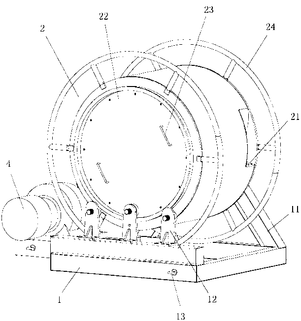
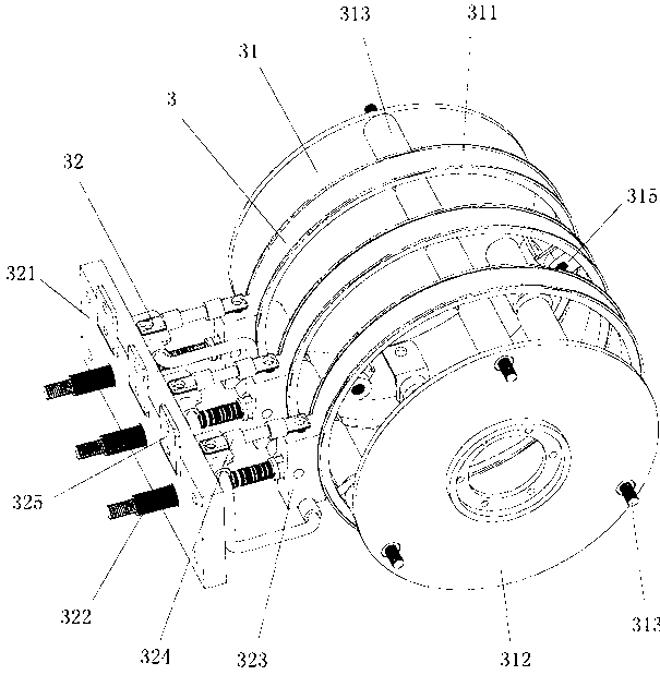
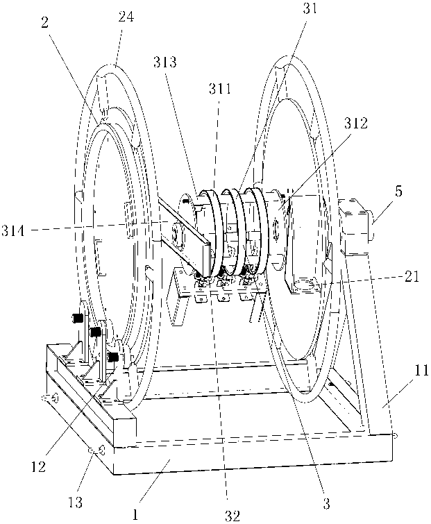
[0015] Such as figure 1 , figure 2 As shown, the present invention includes a base 1, a cable winding bucket 2 arranged on the upper side of the base 1, a slip ring device 3, and a reel driving device 4 arranged on one side of the base 1, and cable retaining rings are arranged on both sides of the cable winding bucket 2 24. It can prevent the cable from falling off. The middle part of one side of the cable barrel 2 is supported on the inner end of the main shaft 5 through bearings and bearing discs (not shown in the figure), and the outer end of the main shaft 5 is supported on the top of the bracket 11 on the side of the base 1. The main shaft 5 It is a hollow structure, and the other side of the base 1 is provided with three winding auxiliary wheels 12 at intervals. It can be relatively rolled, and the three auxiliary wheels 12 of the reel are arranged one above th...


PUM


Abstract

The invention discloses a low-voltage cable reel with an embedded slip ring. The low-voltage cable reel comprises a base, a cable winding bucket, a slip ring device and a reel driving device, wherein the slip ring device is arranged in the cable winding bucket, and comprises a slip ring mechanism and an electric brush mechanism; the slip ring mechanism comprises a slip ring group consisting of a plurality of slip rings, a bearing disk, a plurality of fixing bolts and a fixed plate; the plurality of fixing bolts are used for fixedly connecting the slip ring group with the bearing disk; the fixed plate is fixed on the inner wall of the cable winding bucket; one end of the slip ring device is supported on the middle part of the fixed plate, and the other end of the slip ring device is supported at the inner end of a main shaft; the electric brush mechanism comprises an insulating bracket, a plurality of electric brush spring groups, a plurality of electric brushes and a plurality of flexible current conveying belts; the insulating bracket is fixed on the inner wall of the cable winding bucket; and the plurality of electric brushes are contacted with corresponding slip rings respectively. According to the low-voltage cable reel, the slip ring device is arranged in the cable winding bucket, so that the low-voltage cable reel is simple and reasonable in structure, is easy and convenient to operate, and is safe and reliable; and the other side of the cable winding bucket is provided with an access cover, and the inside of the cable winding bucket can be overhauled or replaced by opening the access cover only, so that high working efficiency is achieved.

Description

technical field [0001] The invention relates to a cable reel, in particular to a low-voltage cable reel with a built-in slip ring, and belongs to the technical field of cable retracting and unwinding equipment. Background technique [0002] At present, the known low-voltage cable reels are divided into two types: end face slip ring type and external radial slip ring type. The radial slip ring reel has potential safety hazards because the cable at the inlet port is not directly connected to the slip ring, and the slip ring device is located on the end face of the cable winding barrel, which increases the volume of the reel. The structure of the slip ring assembly of the above two reeling cars is unreasonable and poor in watertightness. At the same time, when replacing or overhauling the inside of the cable drum, all the cables wound on the cable drum must be removed, which is a heavy and cumbersome workload. Contents of the invention [0003] The object of the present inve...

Claims


Application Information

Patent Timeline
IPC IPC(8): H02G11/02
Inventor 章广春刘明邓稳王立新
Owner JIANGYIN KAIDA ELECTRIAL & MECHANICAL MFG CO LTD
Learn More