
Double-acting refrigeration compressor

A refrigeration compressor, double-acting technology, used in mechanical equipment, machines/engines, liquid fuel engines, etc., can solve the problem that the cylinder parts cannot move relatively

Active Publication Date: 2013-09-04
INFICON INC
View PDF11 Cites 20 Cited by
  • Summary
  • Abstract
  • Description
  • Claims
  • Application Information

AI Technical Summary

Problems solved by technology

The cylinder parts cannot move relative to each other

Method used


Image

  • Double-acting refrigeration compressor
  • Double-acting refrigeration compressor
  • Double-acting refrigeration compressor

Examples


Embodiment Construction

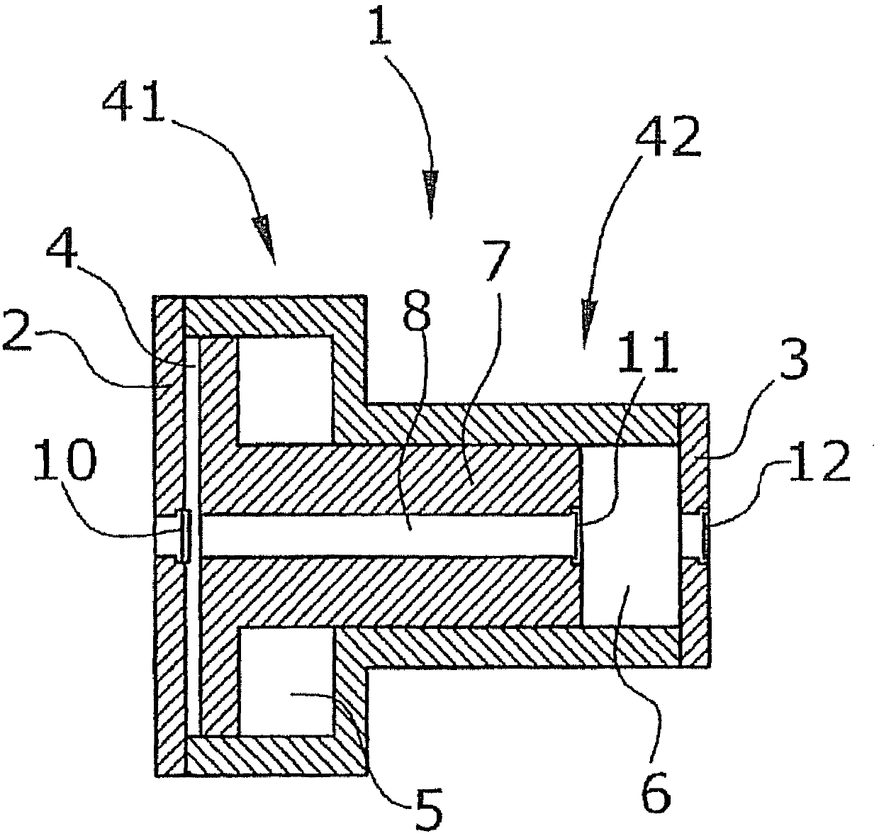
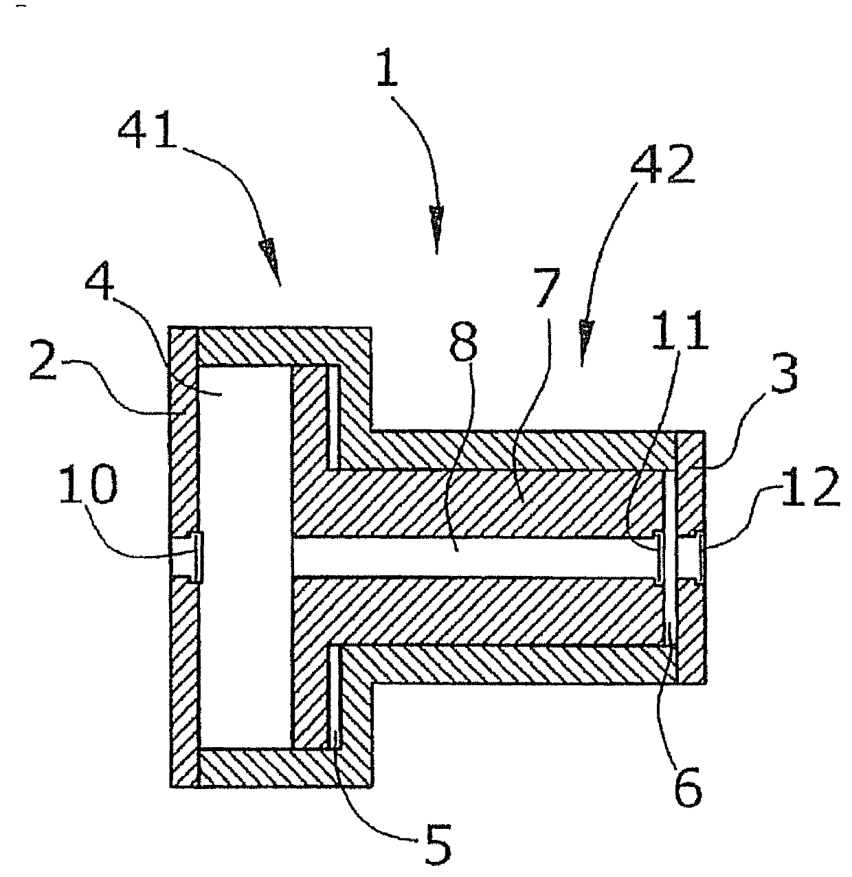
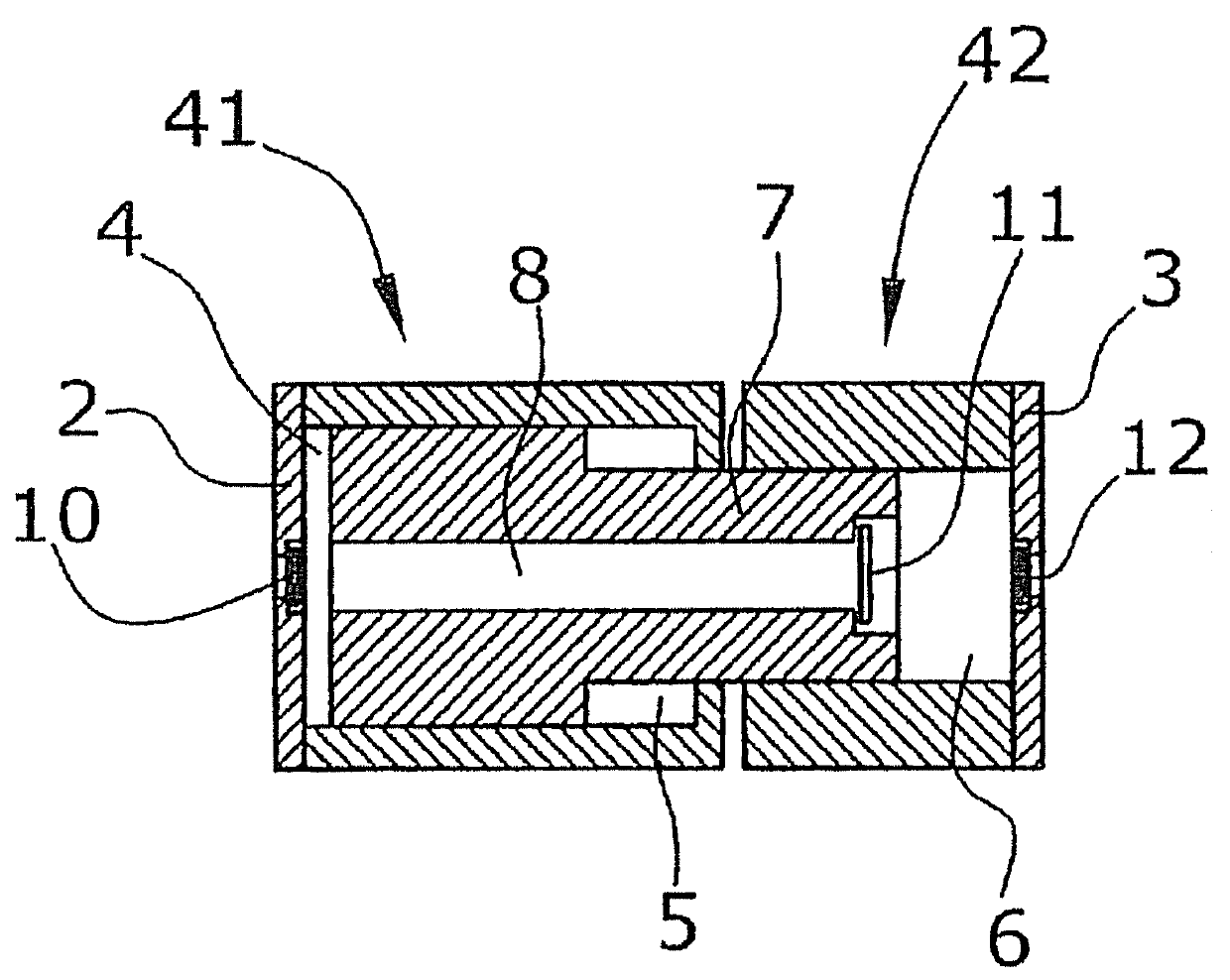
[0030] The refrigeration compressor of the first embodiment is as figure 1 and 2 As shown, the compressor system comprises a step-in cylinder 1 in which a piston 7 with a central flow channel 8 is guided axially. The cylinder is terminated by a suction valve plate 2 in which a suction valve 10 is inserted and a discharge valve plate 3 in which a discharge valve 12 is inserted. The flow channel 8 is terminated by a further valve 11 on the outlet side.

[0031] In this arrangement, the larger-diameter left part of the step-in cylinder 1 forms the first cylinder part 41 and the smaller-diameter right part of the step-in cylinder 1 forms the second cylinder part 42 . In this way, the two cylinder parts 41 , 42 are integrally connected to form the cylinder 1 .

[0032] The basic functions of this double-acting single-row free-piston compressor are described as follows:

[0033] Via drive means not yet described here, the piston will perform a linear oscillation. This can be re...


PUM


Abstract

The refrigeration compressor is a double-acting refrigeration compressor, comprising a piston (7), which is freely guided on two cylinder sections (41, 42) that are opposite each other and that cannot be moved relative to each other, and which has a flow channel (8) that extends internally through the piston (7), wherein each cylinder section (41, 42) and the piston (7) have at least one check valve (10, 11, 12) along the flow channel (8), wherein the check valves (10, 11, 12) are arranged in such a way that the flow directions thereof are oriented in the same direction.

Description

technical field [0001] This invention relates to double-acting refrigeration compressors. Background technique [0002] The field of refrigerant recovery in cooling systems, especially air-conditioning systems, requires compressors to be able to extract refrigerant from the cooling system and transfer it to the corresponding transport container under the prevailing conditions at the place where the air-conditioning system is used. [0003] To this end, the required compressor needs to generate a gas pressure in the bottle that is greater than the vapor pressure of the refrigerant at various ambient temperatures. In extreme cases, the gas pressure can be significantly greater than 30 bar and it is further assumed that the working pressure reaches 40 bar. [0004] Existing recovery units that transfer refrigerant from the refrigeration system to a recovery vessel have a compressor and a bypass line that shuts the compressor off. Both the compressor line and the bypass line h...

Claims


Application Information

Patent Timeline
IPC IPC(8): F04B25/02F04B31/00F04B39/00F04B53/12F04B53/14
CPCF04B31/00F04B39/0016F04B53/122F04B53/148F04B25/02F04B53/12F04B35/045F04B5/00F04B1/02F04B17/04F04B25/04F04B17/046F04B25/005F04B5/02F04B27/02
Inventor 维尔纳·施密特
Owner INFICON INC
Learn More