bicycle transmission gear

A speed change mechanism and bicycle technology, which is applied to vehicle gearboxes, wheel transmissions, vehicle components, etc., can solve the problems of function loss, inconsistent work directions of spiral bevel gears, and no formation, etc., so as to improve function utilization and enhance Transmission efficiency and carrying capacity, the effect of increasing the gear occlusal contact surface

Inactive Publication Date: 2015-10-28
杭州华杭电子电器有限公司
View PDF7 Cites 0 Cited by
  • Summary
  • Abstract
  • Description
  • Claims
  • Application Information

AI Technical Summary

Problems solved by technology

[0002] Today's gear-shaft-driven bicycles are all a set of bevel gears, a first driving wheel and a first driven wheel meshing with each other. The definition of bevel gear rotation is 45-degree meshing and 90-degree vertical transmission. Only such transmission can achieve stable operation. Powerful rotation, the combination of bevel gears on automobiles and ships follows this definition, but the combination of bevel gear shafts on bicycles today does not follow this definition, the first driving wheel and the first driven wheel do not form a 45-degree angle, let alone The upper 90-degree transmission, the two-wheel contact surface only bites one-third, because the bicycle does not have much load capacity, the designer did not use his brains in this regard, and as a result, the labor-saving function of the bevel gear transmission was not fully utilized; more importantly The most important thing is that the reaction force generated between the spiral bevel gears is inconsistent with the direction of work, forming a 90-degree lateral thrust, which is the loss of function

Method used


Image

  • bicycle transmission gear
  • bicycle transmission gear
  • bicycle transmission gear

Examples


Embodiment Construction

[0020] The present invention will be further described below in conjunction with the accompanying drawings of the description.

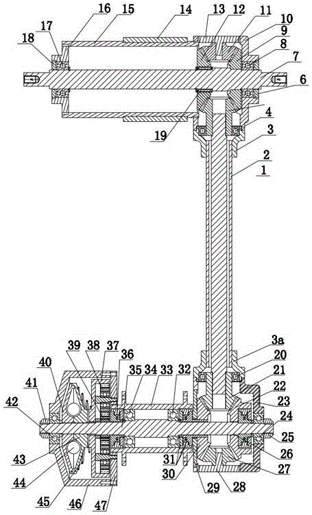
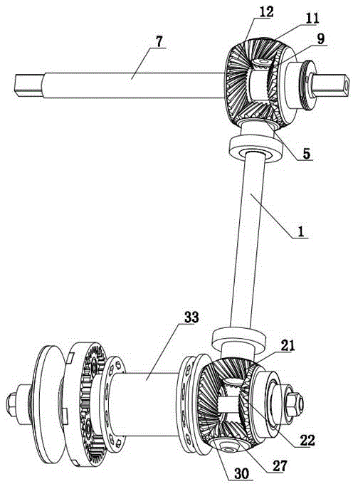
[0021] As shown in the figure, the bicycle transmission transmission mechanism includes a drive shaft 7 connected to two pedals, a driven shaft 1 connected to the rear wheel of the bicycle, a first drive wheel 9 is fixedly installed on the drive shaft 7, and the first drive wheel 9 is connected to the first drive shaft 9. A driven wheel 5, the first driven wheel 12, and the first booster wheel 11 are meshed with each other to form the first group of zigzag gear sets. The first driven wheel 5 is fixedly installed on the driven shaft 1, and the first driven wheel 12 and the driving shaft 7 Rotation fit, the first power-assisted wheel 11 is installed on the bicycle frame; The power-assisted wheels 30 intermesh and drive to form the second group of zigzag gear sets. The second driven wheel 22 is fixedly connected with the rear rotating shaft 35 through t...


PUM


Abstract

The invention discloses a bicycle transmission speed changing mechanism, and belongs to the technical field of bicycles. The bicycle transmission speed changing mechanism comprises a driving shaft connected with two pedals and a driven shaft connected with the rear wheel of a bicycle, and is characterized by comprising a first square gear set and a second square gear set, and further comprising a speed changing mechanism composed of a clutch and a speeding changing gear set. The bicycle transmission speed changing mechanism is simple and reasonable in structure. Two square gear sets are adopted, four gears are connected in a transmission and meshing mode to form stable transmission of the square gear sets, kinetic energy can be recycled, and therefore the using ratio of the kinetic energy is greatly improved, and a user can easily ride the bicycle in a labor-saving mode. The speed changing mechanism is arranged, riding of the bicycle is easily started in a labor-saving mode, and after advancing, the speed of the bicycle becomes higher. The gears are spiral bevel gears, are meshed in a 45-degree mode and are perpendicularly connected in a transmission mode, and therefore the meshing contact areas of the gears are increased, and the transmission efficiency and bearing capability of the gears are further improved. The bicycle transmission speed changing mechanism is reliable in working, compact in structure, energy-saving, material-saving, wear-resisting, long in service life and small in noise.

Description

technical field [0001] The invention belongs to the technical field of bicycles, in particular to a bicycle transmission speed change mechanism. Background technique [0002] Today's gear shaft-driven bicycles are all a set of bevel gears, a first driving wheel and a first driven wheel meshing with each other. The definition of bevel gear rotation is 45-degree meshing and 90-degree vertical transmission. Only such transmission can achieve stable operation. Powerful rotation, the combination of bevel gears on automobiles and ships follows this definition, but the combination of bevel gear shafts on bicycles today does not follow this definition, the first driving wheel and the first driven wheel do not form a 45-degree angle, let alone The upper 90-degree transmission, the contact surface of the two wheels only bites one-third, because the bicycle does not have much load capacity, the designer does not use his brains in this regard, and as a result, the labor-saving function ...

Claims


Application Information

Patent Timeline
Patent Type & Authority Patents(China)
IPC IPC(8): B62M11/14
Inventor 陈元朝谢华跃郭黎
Owner 杭州华杭电子电器有限公司
Why Eureka
Try Eureka