CNC discharging disc inserting device for PCB tiny-drill groove forming

A technology of blanking and inserting disks, applied in conveyor control devices, transportation and packaging, conveyor objects, etc., can solve the problems of cutting edge or thread angle gap, inconvenient manual operation, PCB micro-drilling easily hurting hands, etc. , to achieve the effect of increasing the rate of material collection, reducing energy consumption and reducing costs

Active Publication Date: 2013-09-11
GUANGDONG DTECH TECH CO LTD
View PDF6 Cites 8 Cited by
  • Summary
  • Abstract
  • Description
  • Claims
  • Application Information

AI Technical Summary

Problems solved by technology

[0003] In the production process of PCB, a micro-drill is needed, and the micro-drill with a drill diameter of less than 3.175mm. At present, in the process of PCB micro-drilling, especially after the PCB micro-drill is grooved by CNC, it is usually manually operated. Remove the processed PCB micro-drill from the clamping mechanism of the CNC spindle product. Since the diameter of the PCB micro-drill is relatively small, manual operation is very inconvenient, and the PCB micro-drill is easy to hurt the hand. Once the PCB micro-drill is stuck in the hand, It is difficult to be taken out, and it must be taken out with special tools in hospital surgery; in addition, due to the hard and brittle material characteristics of tungsten steel, a slight bump (collision) during manual operation may cause the cutting of the processed PCB micro-drill Notch in the edge or thread corner, and not easy to detect

Method used


Image

  • CNC discharging disc inserting device for PCB tiny-drill groove forming
  • CNC discharging disc inserting device for PCB tiny-drill groove forming

Examples


Embodiment Construction

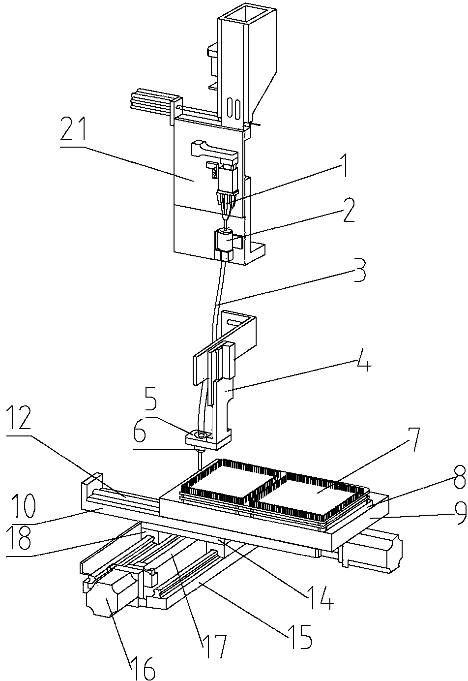
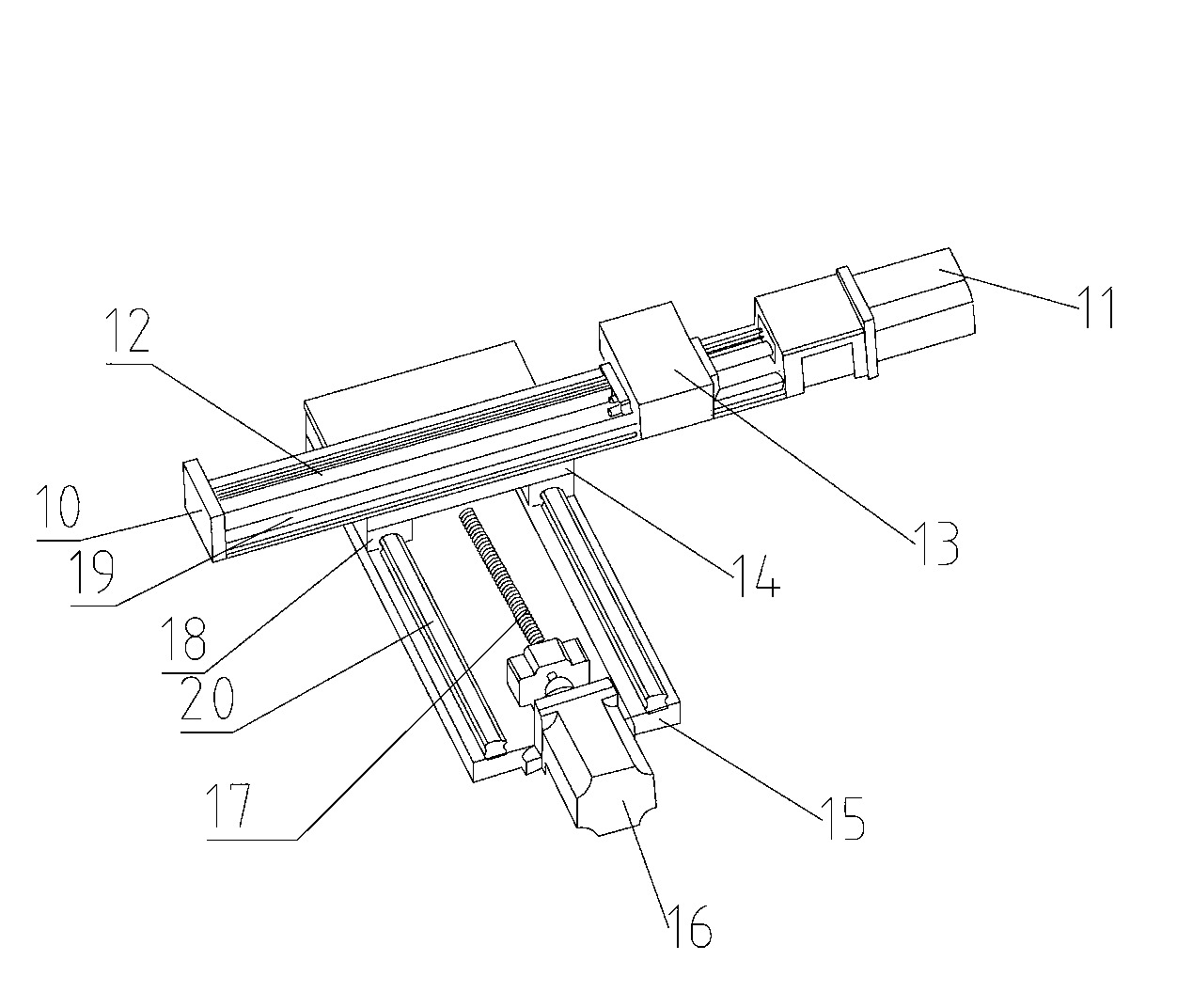
[0021] Such as figure 1 As shown, the CNC blanking device for slotting PCB micro-drilling includes a blanking mechanism and a receiving mechanism located below the blanking mechanism. The blanking mechanism includes a blanking frame 21, and the blanking frame 21 is installed There are feeding pneumatic finger 1 and receiving hopper 2. The receiving hopper 2 is below the pneumatic finger 1. The bottom end of the receiving hopper 2 is provided with a feeding port, and a feeding pipe 3 is installed at the feeding port; the above-mentioned receiving mechanism includes Receiving upper and lower cylinders 4, the XY moving device located under the receiving upper and lower cylinders 4, and the tray point plate 8 installed on the XY moving device for carrying the tray; the bottom of the receiving upper and lower cylinders 4 is equipped with a guide groove 6. A ring-shaped metal detection sensor 5 is arranged on the periphery of the material guide trough 6, and the bottom end of the fe...


PUM


Abstract

The invention relates to the field of PCB tiny-drill machining, in particular to a CNC discharging disc inserting device for PCB tiny-drill groove forming. The CNC discharging disc inserting device for PCB tiny-drill groove forming comprises a discharging mechanism and a receiving mechanism. The discharging mechanism comprises a discharging machine frame. Discharging pneumatic fingers and a collecting hopper are installed on the discharging machine frame. The collecting hopper is arranged below the pneumatic fingers. A discharging opening is formed in the bottom end of the collecting hopper. A discharging pipe is installed on the discharging opening. The material receiving mechanism comprises a vertically moving receiving air cylinder, an X-Y moving device located below the vertically moving receiving air cylinder and a material disc point location board arranged on the X-Y moving device and used for bearing a material disc. The bottom end of the vertically moving receiving air cylinder is provided with a material guiding groove. The bottom end of the discharging pipe extends into the material guiding groove, so that automation and systematization of the PCB tiny-drill machining are achieved, production efficiency is improved, labor cost is reduced, the quality of a PCB tiny drill is improved, the machining cost of the PCB tiny drill is reduced and the safety of an operator is guaranteed in the process of PCB tiny-drill machining.

Description

technical field [0001] The invention relates to the field of PCB micro-drilling processing, in particular to a CNC blanking and inserting device for slotting PCB micro-drilling. Background technique [0002] PCB, the Chinese name is printed circuit board, is an important electronic component, a support for electronic components, and a provider of electrical connections for electronic components. [0003] In the production process of PCB, a micro-drill is needed, and the micro-drill with a drill diameter of less than 3.175mm. At present, in the process of PCB micro-drilling, especially after the PCB micro-drill is grooved by CNC, it is usually manually operated. Remove the processed PCB micro-drill from the clamping mechanism of the CNC spindle product. Since the diameter of the PCB micro-drill is relatively small, manual operation is very inconvenient, and the PCB micro-drill is easy to hurt the hand. Once the PCB micro-drill is stuck in the hand, It is difficult to be tak...

Claims


Application Information

Patent Timeline
Patent Type & Authority Applications(China)
IPC IPC(8): B65G47/74B65G43/08
Inventor 王俊锋王雪峰李政
Owner GUANGDONG DTECH TECH CO LTD
Why Eureka
Try Eureka