Automatic troweling machine

A plastering machine, automatic technology, applied in the direction of construction, building structure, etc., can solve the problems of low efficiency, easy falling off of the plastering surface, inconvenient movement, etc., and achieve the effect of reducing the conveying link, solving the decrease in strength and high labor efficiency.

Inactive Publication Date: 2015-04-15
王刚
View PDF6 Cites 0 Cited by
  • Summary
  • Abstract
  • Description
  • Claims
  • Application Information

AI Technical Summary

Problems solved by technology

[0003] In order to solve the problems of the existing wall plastering methods such as low efficiency, inconvenient movement, and easy falling off of the plastering surface, the present invention designs an automatic plastering machine

Method used


Image

  • Automatic troweling machine
  • Automatic troweling machine
  • Automatic troweling machine

Examples


Embodiment Construction

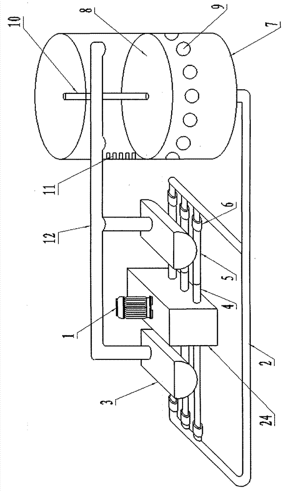
[0027] The structure of the present invention will be explained in detail below in conjunction with the accompanying drawings. An automatic plastering machine includes a feeding system, a storage system and a plastering system, such as figure 1 It is a schematic diagram of the connection structure between the feeding system and the storage system of the present invention;

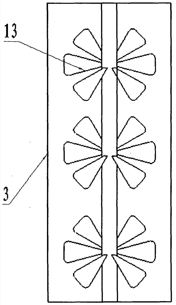
[0028] Each system is connected by a delivery pipeline 2. The feeding system includes a power output device 1 connected to the piston cylinder and a feeding box 3. The piston cylinder 4 is connected to one end of the feeding pipeline 5. The feeding box is fixed above the feeding pipeline and passed through a one-way valve. 6 Connect with the feeding pipeline, and the feeding pipeline is connected with the conveying pipeline through a one-way valve; Figure 4 It is a side view of the structure of the feeding box of the present invention; the storage system includes a storage tank 7 connected to the bottom of...


PUM


Abstract

The invention discloses an automatic troweling machine comprising a feeding system, a storage system and a troweling system. The systems are connected through a delivery pipe, the feeding system comprises a power output device connected with piston cylinders and feeding boxes, each cylinder is connected with one end of a feeding pipe, the feeding boxes are fixed above the feeding pipes and connected with the same through check valves, and the feeding pipes are connected with the delivery pipe through the check valves. The storage system comprises a storage vat with the bottom connected with the delivery pipe, a pressing plate is disposed in the storage vat, and feeding holes are formed on the side wall of the storage vat and connected with a machine head of the troweling system through the delivery pipe. The troweling system comprises rails and the machine head, the rails include vertical rails transversely sliding on horizontal rails and a machine head rail vertically sliding on the vertical rails, the machine head rail is parallel to the horizontal rails, and the machine head sliding horizontally is connected to the machine head rail. By the designed automatic troweling machine, the problems of low efficiency, inconvenience in moving, proneness to shedding of trowelled surfaces and the like of an existing mode are solved.

Description

technical field [0001] The invention belongs to construction equipment, in particular to an automatic plastering machine. Background technique [0002] The existing wall plastering methods are divided into two categories. The first is pure manual plastering. The main disadvantages of manual plastering are high labor intensity, slow labor efficiency, and long storage time, resulting in two or three water additions. Stirring reduces the strength of the sand ash and wastes the floor ash; the second is mechanical plastering. The existing mechanical plastering has the disadvantages of dead angles, clumsy machinery, inconvenient movement, large floor ash, and unreliable plastering. There are problems such as shedding, manual feeding, and the reduction of mortar strength due to the second or third addition of water and stirring caused by the long time of ash storage. Contents of the invention [0003] In order to solve the problems of low efficiency, inconvenient movement and ea...

Claims


Application Information

Patent Timeline
Patent Type & Authority Patents(China)
IPC IPC(8): E04F21/08
Inventor 王刚
Owner 王刚
Why Eureka
Try Eureka