
Drilling and punching integrated hydraulic drill bit

A technology of hydraulic punching and drilling bits, which is applied in drill bits, drilling equipment, earth-moving drilling, etc., can solve the problems of no secondary crushing capacity, clogging of slag discharge channels, uneven coal output, etc., achieving simple structure and preventing hole jamming , the effect of shortening the construction time

Inactive Publication Date: 2013-09-11
HENAN POLYTECHNIC UNIV
View PDF11 Cites 17 Cited by
  • Summary
  • Abstract
  • Description
  • Claims
  • Application Information

AI Technical Summary

Problems solved by technology

[0003] Domestic published patent documents CN201513195U and CN101532391 respectively disclose a drilling-punching integrated hydraulic punching bit, but there are the following defects: 1. the structure is relatively complicated, and the hydraulic loss is serious; 2. in the environment where coal and water are mixed Blockage is prone to occur, and there are certain problems in field use; ③There is no secondary crushing capacity, and the large slag blocks (such as pyrite nodules) formed by punching can easily cause blockage of slag discharge channels, and even hole holding, drill pinching, and spray holes , Uneven coal discharge, etc.
The published patent document CN102678048A discloses a multi-stage hydraulic punching drill with secondary crushing capability, which reduces the probability of holding the hole and pinching the drill to a certain extent, but still has the problem of replacing the punching nozzle and consuming man-hours

Method used


Image

  • Drilling and punching integrated hydraulic drill bit
  • Drilling and punching integrated hydraulic drill bit
  • Drilling and punching integrated hydraulic drill bit

Examples


Embodiment Construction

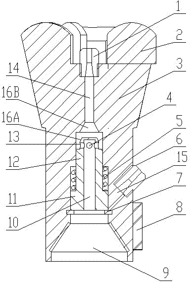
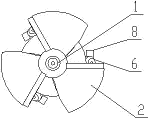
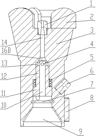
[0015] Depend on Figure 1-Figure 3 The shown drilling-punching integrated hydraulic punching drill includes a drill body 3 extending forward and backward. The front end of the drill body 3 is provided with blades 2, and the blades 2 are evenly spaced around the central axis of the drill body 3. The blade 2 is provided with a cemented carbide blade. An axially extending through hole is provided throughout the drill bit body 3 , the axis of the through hole is the central axis of the drill bit body 3 , and the through hole also extends forward and backward. The through hole includes a nozzle hole portion 14 located in the front section, a valve body hole section located in the middle section and a reaming part 9 located in the rear section, and the reaming part 9 is a tapered threaded hole expanding outward on the rear side. The nozzle hole part 14 is a cylindrical hole, the rear port of the nozzle hole part 14 is a tapered opening 16B, and the tapered threaded hole of the rea...


PUM


Abstract

The invention discloses a drilling and punching integrated hydraulic drill bit which comprises a drill bit body. A through hole, extending axially, penetrates the whole drill bit body and comprises a nozzle hole portion in the front and a valve hole portion in the middle. The back end of the nozzle hole is designed into a conical surface, and a reversing valve is arranged in the valve hole portion and comprises a protrusion block and a spring. The protrusion block is provided with a connection hole extending axially and a side hole communicated with the connection hole, the front end of the connection hole is blind, the front end of the protrusion block is designed into a conical surface which is in fitting seal with the conical surface of the back end of the nozzle hole portion. The drill bit body is further provided with a side nozzle hole, and an inner end port of the side nozzle hole leads to a big hole of the valve hole portion while an outer end port of the side nozzle hole leads to the surface of the outer ring of the drill bit body. The drilling and punching integrated hydraulic drill bit overcomes defects of existing hydraulic punching devices. Drilling and punching integration is realized by the aid of the automatic reversing valve. Secondary breaking of big cinders is realized by the aid of secondary breaking tools arranged reasonably, so that blocking of discharging passages due to falling of the big cinders is avoided.

Description

technical field [0001] The invention relates to a drilling-punching integrated hydraulic punching drill capable of realizing the integration of drilling and punching and effectively preventing hole plugging, which is suitable for high-efficiency drainage of underground gas in coal mines. Background technique [0002] With the increase of mining depth, coal mine gas disasters are becoming more and more serious. Gas drainage is an important means to prevent and control gas disasters and realize the comprehensive utilization of gas. Among them, the hydraulic punching technology is one of the measures for efficient and safe gas extraction. It uses rock pillars or coal pillars as a safety barrier. When discharged, the coal around the tunnel moves violently towards the tunnel, and at the same time, the expansion deformation of the coal and the relative displacement of the top and bottom plates occur, which causes the ground stress to decrease within a certain range of influence o...

Claims


Application Information

Patent Timeline
Patent Type & Authority Applications(China)
IPC IPC(8): E21B7/18E21B10/38
Inventor 刘明举左伟芹刘彦伟郝富昌赵发军陈文学邓奇根彭信山张永平
Owner HENAN POLYTECHNIC UNIV
Learn More