
Blade swing wing design method and H-type vertical axis wind turbine with blade swing wings

A design method and technology for wind turbines, which are applied to wind turbines, wind turbines, motors and other directions at right angles to the wind direction, can solve problems such as difficulty in self-starting, and achieve reduced manufacturing costs, enhanced self-starting performance, and increased camber and chord length. Effect

Active Publication Date: 2015-05-13
HARBIN INST OF TECH
View PDF7 Cites 0 Cited by
  • Summary
  • Abstract
  • Description
  • Claims
  • Application Information

AI Technical Summary

Problems solved by technology

[0007] The purpose of the present invention is to solve the problem that the existing lift-type vertical axis wind turbine is difficult to self-start at low wind speeds, and at the same time, in order to improve the operating performance of the wind turbine in the lift mode, it proposes a blade swing wing design method and a swing wing H-type vertical axis wind turbine

Method used


Image

  • Blade swing wing design method and H-type vertical axis wind turbine with blade swing wings
  • Blade swing wing design method and H-type vertical axis wind turbine with blade swing wings
  • Blade swing wing design method and H-type vertical axis wind turbine with blade swing wings

Examples


specific Embodiment approach 1

[0025]Specific embodiment one: blade swing wing design method in the present invention comprises following 7 steps:

[0026] 1. Determine the working wind speed of the wind turbine, the resistance moment when the wind turbine starts, the length of the blade, the chord length of the blade and the radius of rotation of the wind rotor;

[0027] 2. According to the working wind speed of the wind turbine, the length of the blades, the resistance moment of the wind turbine and the radius of rotation of the wind wheel to determine the mathematical model of the wind turbine startup;

[0028] 3. Determine the friction torque when the swing wing rotates, the density of the material used to process the swing wing, the thickness of the swing wing and the speed of the wind wheel when the swing wing is closed;

[0029] 4. According to the length of the blade, the friction torque when the swing wing rotates, the density of the material used to process the swing wing and the speed of the wind...

specific Embodiment approach 2

[0033] Embodiment 2: This embodiment is a further description of Embodiment 1. In step 1, the working wind speed of the wind turbine is calculated according to the average wind speed of the wind condition in the area where the wind turbine is located; conditions and the technical data of the supporting generator, calculate the resistance moment that the wind turbine needs to overcome when it is aerodynamic; according to the specific geometric parameters of the wind turbine rotor that needs to be installed with blades, measure the length of the blade, the chord length of the blade and the radius of gyration of the wind wheel.

specific Embodiment approach 3

[0034] Specific implementation mode three: this implementation mode is a further description of specific implementation mode one or two, and the calculation formula of the wind turbine starting mathematical model described in step two is: ; where, M s is the resistance torque that needs to be overcome when the wind turbine starts, V a is the working wind speed of the wind turbine, C 1 is the width of the swing wing, H is the length of the blade, and R is the radius of gyration of the wind wheel.


PUM


Abstract

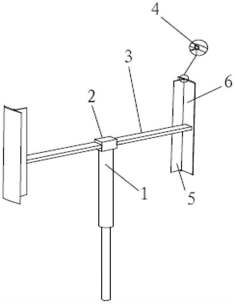
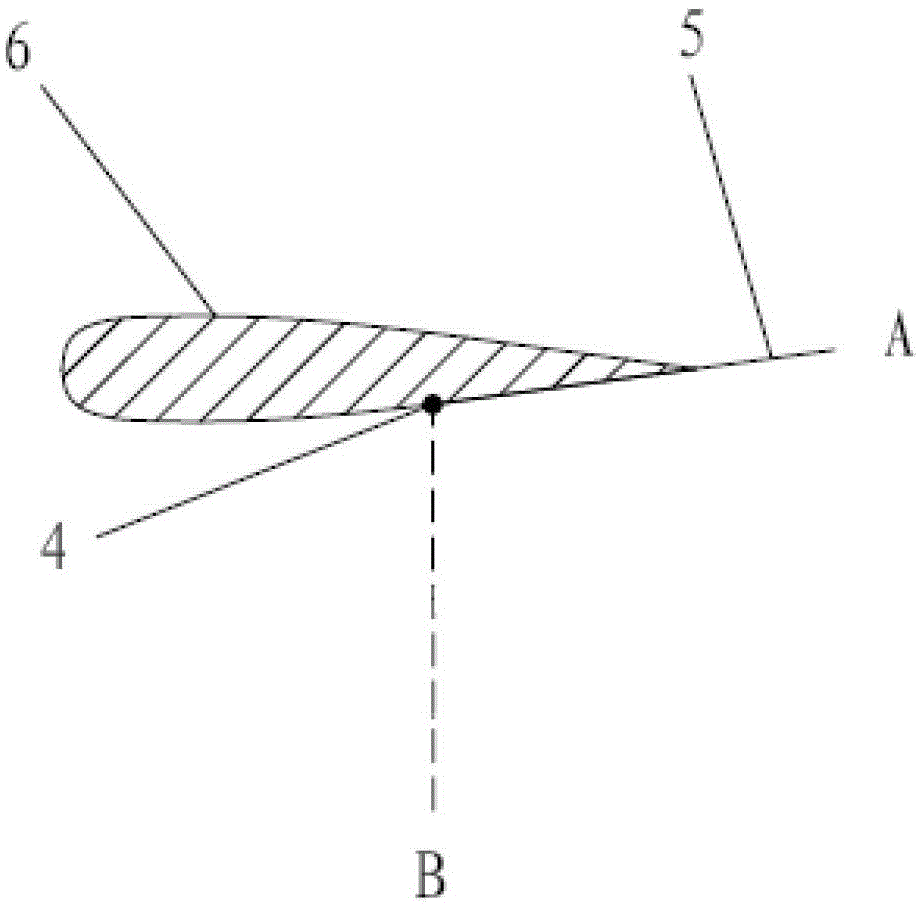
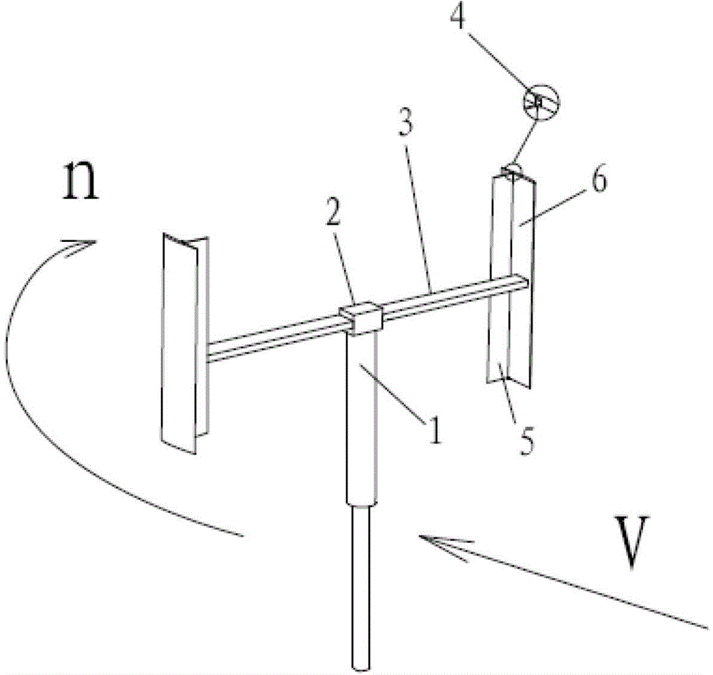
The invention relates to a blade swing wing design method and an H-type vertical axis wind turbine with blade swing wings, and aims at solving the problem that an existing lift type vertical axis wind turbine is difficult to start by self at low wind speed, and improving operation performance of the wind turbine in a lift mode. The blade swing wing design method includes seven steps for determining structural parameters of each part of a swing wing of each blade. The H-type vertical axis wind turbine with the blade swing wings comprises a center shaft, a hub, N support arms, N rotation pairs, N swing arms and N blades, wherein N is an integer, and 2< / =N< / =6. The N blades are straight blades, the N support arms are distributed horizontally and evenly and arranged linearly or in a star shape, one end face of each support arm is fixedly connected to the hub, the hub vertically arranged above the center shaft, the N blades are fixedly connected to the other ends of the N support arms in a one-to-one correspondence manner, and every side end face of each swing wing is mounted on the inner side face of the corresponding blade through one rotation pair. The blade swing wing design method and the H-type vertical axis wind turbine can be applied to the communication field and the technical field of urban wind power utilization.

Description

technical field [0001] The invention relates to a design method of a blade swing wing and an H-type vertical shaft wind machine with a blade swing wing. Background technique [0002] Modern wind turbines are mainly divided into two categories: horizontal axis wind turbines and vertical axis wind turbines. At present, the mainstream commercial wind turbines are all horizontal axis wind turbines. Although horizontal-axis wind turbines are the most widely used, there are still some technical problems, such as difficult maintenance, must have wind-facing devices, and high manufacturing costs. Compared with horizontal axis wind turbines, vertical axis wind turbines have the following potential advantages: (1) No yaw device is needed, and energy from wind from any direction can be absorbed; (2) The power generation system and speed-increasing system of vertical axis wind turbines are located on the ground. Vertical axis wind turbines have more advantages in installation and maint...

Claims


Application Information

Patent Timeline
Patent Type & Authority Patents(China)
IPC IPC(8): F03D3/06
CPCY02E10/74Y02P70/50
Inventor 曲建俊梅毅许明伟
Owner HARBIN INST OF TECH
Learn More