
Integrated yaw type floating wind power plant at sea

A wind farm and yaw technology, applied in wind power generation, wind motor combination, wind generator components, etc., can solve the problems of large tower wind resistance, increased operating costs, and heavy workload at high altitude, so as to reduce personal safety accidents , Reduce maintenance costs, reduce the effect of failure rate

Active Publication Date: 2013-09-11
JIANGSU NEW UNITED HEAVY IND SCI & TECH +1
View PDF13 Cites 15 Cited by
  • Summary
  • Abstract
  • Description
  • Claims
  • Application Information

AI Technical Summary

Problems solved by technology

This kind of platform floats on the offshore sea. The wind turbines using this scheme can only use the yaw at the top of the tower. The cross-section of the tower is a circular or regular polygon structure, and the tower of this shape has large wind resistance and bending resistance. Weak ability
In order to meet the rigidity and strength requirements of the offshore unit for the tower, the tower must be rolled with a thicker steel plate, which will increase the difficulty of rolling and the manufacturing cost
In addition, due to the high failure rate of the yaw system, inconvenient maintenance, and high-altitude operations, the operating cost will increase

Method used


Image

  • Integrated yaw type floating wind power plant at sea
  • Integrated yaw type floating wind power plant at sea
  • Integrated yaw type floating wind power plant at sea

Examples


Embodiment Construction

[0031] The present invention will now be further explained in conjunction with the drawings. These drawings are all simplified schematic diagrams only to illustrate the basic structure of the present invention in a schematic manner, so they only show the constitution related to the present invention.

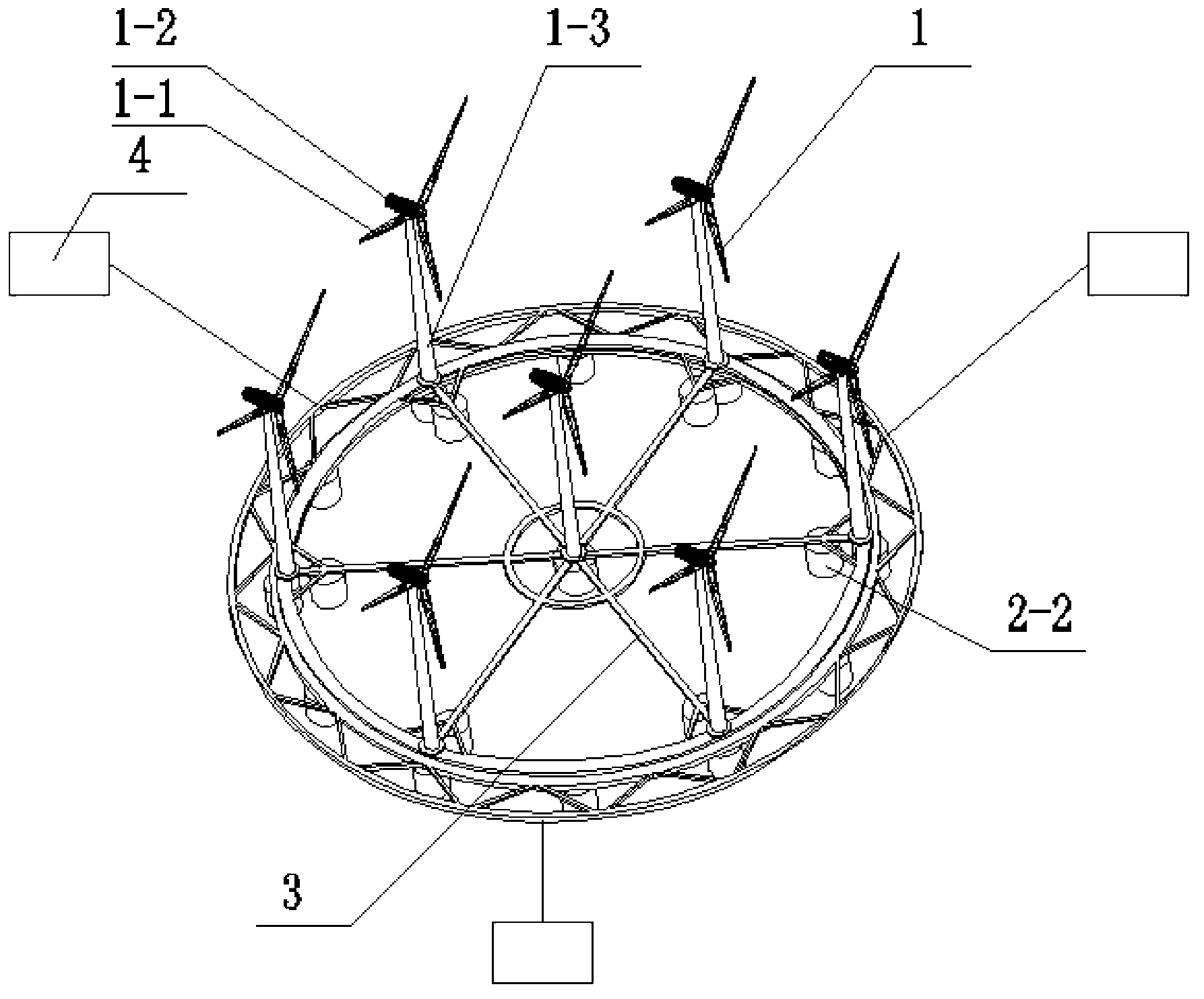
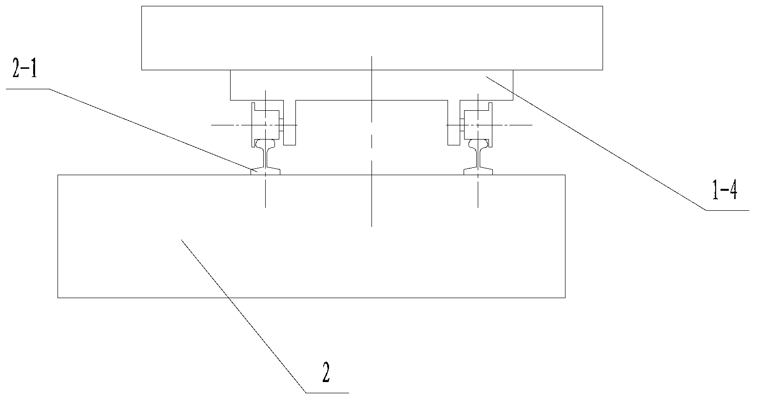
[0032] Such as figure 1 figure 2 As shown, an integral yaw-type offshore floating wind farm has multiple yaw-type wind turbines 1 and a ring-shaped floating platform 2. Each yaw-type wind turbine 1 includes a wind wheel 1-1, a nacelle 1- 2. Tower 1-3, bogie 1-4, wind wheel 1-1 is installed on nacelle 1-2, nacelle 1-2 is fixed on tower 1-3, and the bottom of tower 1-3 is installed on bogie 1-4 on. The bogies 1-4 of each yaw-type wind turbine 1 are mechanically connected by trusses or rods 3. The ring-shaped floating platform 2 includes a ring-shaped track 2-1, a plurality of buoys 2-2 supporting the ring-shaped track, the ring-shaped track 2-1 is installed on the plurality of buo...


PUM


Abstract

The invention relates to an integrated yaw type floating wind power plant at sea. The integrated yaw type floating wind power plant at seat is provided with a plurality of yaw type wind generating sets and an annular floating platform. Each yaw type wind generating set comprises wind wheels, an engine room, a tower bowl and a steering frame. The wind wheels are installed on the engine room, the engine room is fixed on the tower bowl, and the bottom of the tower bowl is installed on the steering frame. The annular floating platform comprises an annular rail and a plurality of floating bowls used for supporting the annular rail. The steering frame of each yaw type wind generating set runs around the circle center of the annular floating platform on the annular rail in an annular mode. Metal space trusses or grid structures are adopted for body structures of the tower bowls, and each metal space truss or each grid structure is composed of steel plates with different thicknesses. A respective single yaw system of each wind generating set is saved, the failure rate can be reduced, and maintenance cost and personal safety accidents can be reduced. Strength and rigidity of the tower bowls can be greatly improved, and with the same number of steel products, anti-bending inertia moments of the tower bowls can be greatly improved.

Description

Technical field [0001] The invention relates to the technical field of offshore wind power generation, in particular to an integral yaw type offshore floating wind farm. Background technique [0002] The offshore wind resources are very rich. With the rapid development of the wind power industry, the development and utilization of wind resources has gradually shifted from land to ocean. China's offshore wind energy reserves are about 750 million kilowatts, equivalent to three times the onshore wind power reserves. The basic types of offshore wind turbines usually include gravity fixed, pillar fixed and floating foundations. At present, conventional wind turbines are still installed on the foundation. [0003] In order to maximize the wind energy of the wind turbine, the wind turbine needs to use a yaw system to keep the wind wheel always in the windward state. The yaw system is usually installed between the nacelle underframe and the top of the tower. The aerodynamic drive device...

Claims


Application Information

Patent Timeline
Patent Type & Authority Applications(China)
IPC IPC(8): F03D9/00F03D11/00
CPCY02E10/72Y02E10/727Y02E10/728
Inventor 周鹏李平郭廷福吕世林刘晓龙
Owner JIANGSU NEW UNITED HEAVY IND SCI & TECH
Learn More