Supercharge Your Innovation With Domain-Expert AI Agents!

Mechanism for driving double pumps

A driving mechanism and driving shaft technology, which is applied in the direction of machines/engines, pumps, pump devices, etc., can solve the problems of high cost, redundant structure, large volume, etc., and achieve the effects of low cost, compact structure, and convenient manufacturing and assembly

Active Publication Date: 2013-09-11
CHINA FIRST AUTOMOBILE
View PDF6 Cites 0 Cited by
  • Summary
  • Abstract
  • Description
  • Claims
  • Application Information

AI Technical Summary

Problems solved by technology

The drive of the supply pump and the emptying pump mostly adopts one-to-one drive. For a dual-pump system that operates independently, if two sets of the same or different drive mechanisms are used to operate, the system will be large in size, redundant in structure, and high in cost.

Method used


Image

  • Mechanism for driving double pumps
  • Mechanism for driving double pumps
  • Mechanism for driving double pumps

Examples


Embodiment Construction

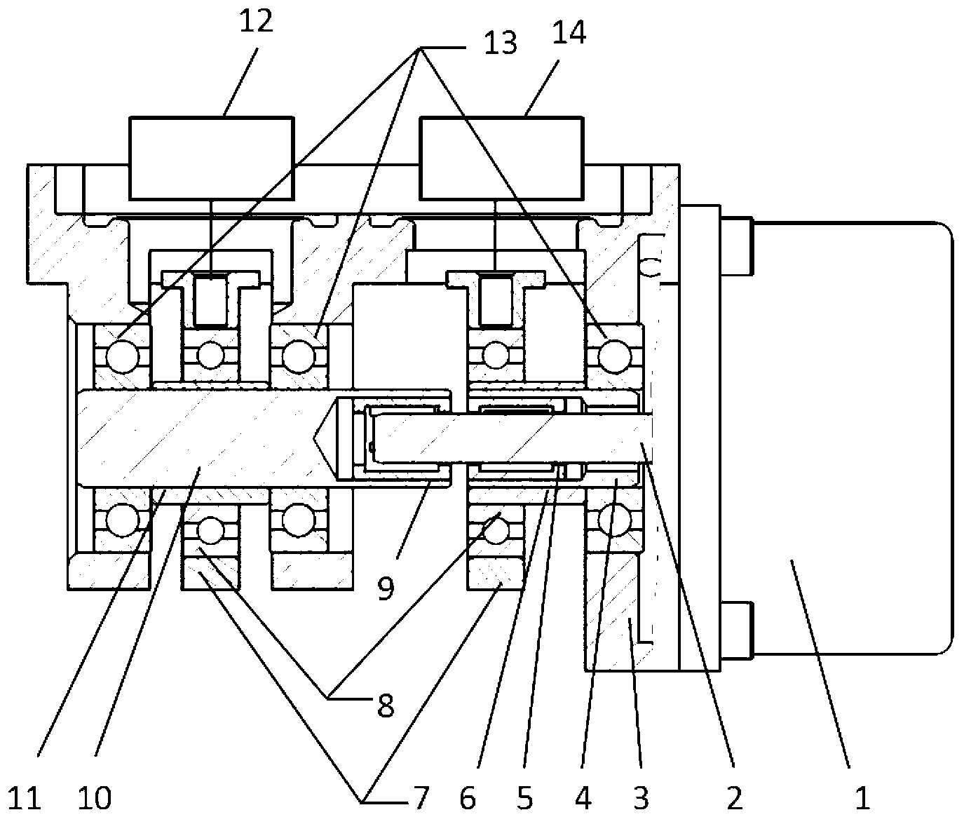
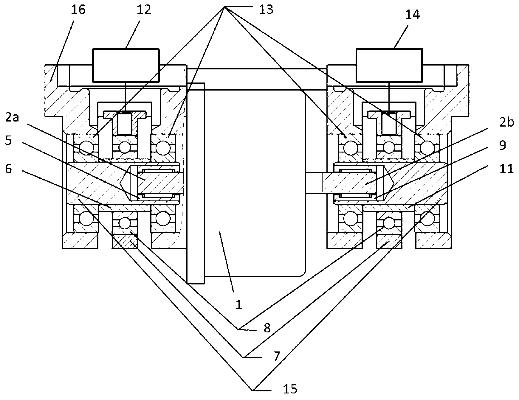
[0018] Such as figure 1 As shown, the present invention mainly consists of motor 1, motor shaft 2, bracket 3, drive shaft I4, drive shaft II10, one-way rotation device I5 and one-way rotation device II9, eccentric cam I6, eccentric cam II11, connecting rod 7, Cam bearing 8, support bearing 13 form the driving mechanism of a set of double pumps.

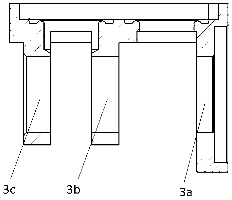
[0019] The motor 1 is installed on the bracket 3, the one-way rotating device I5 and the one-way rotating device II9, preferably the corresponding one-way bearing I and the one-way bearing II, are mounted on the drive shaft I4 and the drive shaft II10 in opposite directions, respectively. In the central hole on the side, the motor shaft 2 is coaxially connected with the one-way bearing I and the one-way bearing II. Pump II12 is a pressure supply pump, and pump I14 is a non-pressure supply pump, which is regarded as an emptying pump. This method can be realized by three support bearings 13 respectively installed in the bearing races 3...


PUM


Abstract

The invention discloses a mechanism for driving double pumps. The mechanism for driving the double pumps comprises a bracket, a motor, a motor shaft, driving shafts and eccentric cams and is characterized in that the motor is installed on the bracket, the two pumps are further arranged on the bracket, two one-way rotating devices which are oppositely arranged are arranged on the motor shaft of the motor and respectively drive the corresponding driving shafts and respectively transmit power to the corresponding eccentric cams, and the eccentric cams respectively drive the corresponding pumps. The mechanism for driving the double pumps has the advantages of being compact in structure, convenient to manufacture and assemble, low in cost, and capable of achieving the function of switching the flow direction of supplied liquid when being used for driving the independently-operated double pumps.

Description

technical field [0001] The invention relates to a driving mechanism, which is suitable for the driving of a double pump that operates independently and needs to be switched. Background technique [0002] With the increasingly serious environmental problems and energy crisis, and stricter emission regulations, more and more energy-saving and emission-reduction technologies are applied to vehicles, among which SCR (Selective Catalytic Reduction) technology is a technology to reduce nitrogen oxide emissions , SCR technology is to spray urea solution, a reducing agent, into the exhaust pipe to release ammonia gas, which reacts with nitrogen oxides in the exhaust gas in the SCR catalytic converter to form nitrogen and water, thereby purifying the exhaust gas. nitrogen oxides in the air. Since the freezing point of urea solution, a reducing agent, is -11°C, when the temperature of the external environment is lower than this temperature, the urea solution will precipitate and crys...

Claims


Application Information

Patent Timeline
Patent Type & Authority Applications(China)
IPC IPC(8): F04B17/03F04B23/04
Inventor 朱明健居钰生缪雪龙夏少华袁宝良姚本容孔亮陈霍胡振奇
Owner CHINA FIRST AUTOMOBILE
Features
  • R&D
  • Intellectual Property
  • Life Sciences
  • Materials
  • Tech Scout
  • Unparalleled Data Quality
  • Higher Quality Content
  • 60% Fewer Hallucinations
Learn More