
Oil tank for leak test

A technology of fuel tank and tank body, which is applied in the direction of fuel supply tank device, pipeline support, pipe/pipe joint/pipe fitting, etc., can solve the problems of manual fixation and inconvenience of trachea, and achieve the effect of ensuring load-bearing strength, improving efficiency and saving manpower.

Active Publication Date: 2015-07-22
SUZHOU SUTENG ELECTRONICS TECH
View PDF8 Cites 0 Cited by
  • Summary
  • Abstract
  • Description
  • Claims
  • Application Information

AI Technical Summary

Problems solved by technology

The air leakage inspection of the workpiece is an important inspection item before or during the use of the stored air workpiece. Traditionally, a special liquid container is required. The air pipe of the workpiece is inserted below the liquid level in the container. After ventilation, observe with the naked eye whether there is foaming. A special liquid container is required, and the trachea needs to be fixed manually, which is very inconvenient

Method used


Image

  • Oil tank for leak test
  • Oil tank for leak test
  • Oil tank for leak test

Examples


Embodiment 1

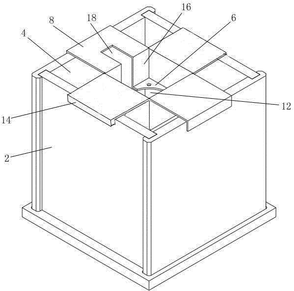
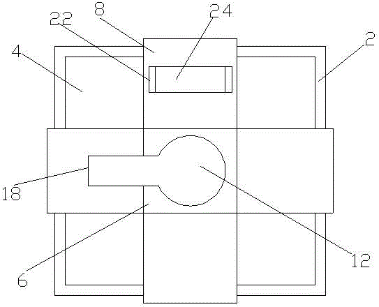
[0017] Such as figure 1 As shown, an oil tank for air leakage inspection includes a square hollow box 2 with an open upper end, and the box 2 has a cavity 4 for accommodating liquid. The fuel tank also includes a gas pipe fixing frame that can be erected on the upper end of the casing 2 . The trachea fixing frame includes a plate-shaped body 6 and four support plates 8 uniformly arranged on the circumference of the body 6 and extending laterally outward. The middle part of the body 6 is provided with a trachea fixing hole 12, and the free end of the support plate 8 is provided with a flange 14 vertically. wall.

[0018] When installing the trachea fixing frame, make the four support plates 8 perpendicular to the four sides of the box body 2 and place them on the upper end of the box body 2, and the flange 14 extends downward relative to the support plate 8, just close to the corresponding side of the box body 2 wall outside the wall. Since the four support plates 8 have fl...

Embodiment 2

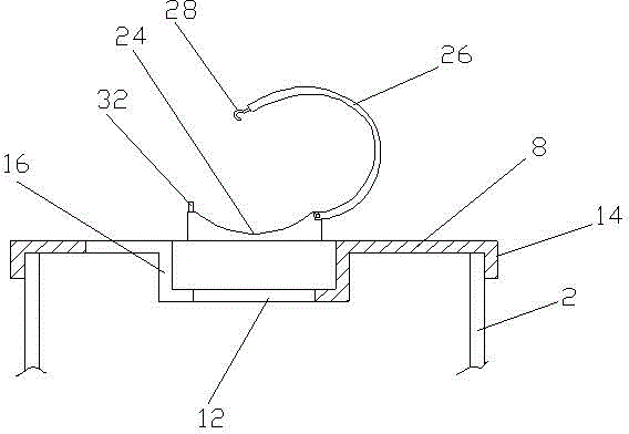
[0022] Such as Figure 1-2 As shown, a fuel tank for air leakage inspection differs from Embodiment 1 in that: a support plate 8 is vertically provided with a block support seat 22, and the top end of the support seat 22 is provided with a groove. The bottom surface 24 of the groove is an arc-shaped curved surface vertically recessed to the support plate 8 . The rear end of the air pipe inserted into the air pipe fixing hole 12 can be erected in the groove of the support seat 22 to prevent the air pipe from shaking left and right under the influence of the air flow, stirring the oil and affecting the inspection results. The arc-shaped curved surface fits the shape of the circular trachea better and increases stability.

Embodiment 3

[0024] Such as figure 1 , 3 As shown, a fuel tank for air leakage inspection differs from Embodiment 2 in that: the support base 22 is provided with a hook 26 that can cooperate with the groove to form a closed loop, and one end of the hook 26 is axially connected to the support base 22 , the other end is provided with a fixed hook 28, and the fixed hook 28 can be movably connected with a fixed ring 32 provided on the support seat 22. During use, at first the crotch 26 is opened relative to the groove, the trachea is erected in the groove, and stretched into the fixing hole, then the crotch 26 is closed relative to the groove, the fixing hook 28 is connected with the fixing ring 32, and then firmly Lock the position of the trachea firmly and prevent the trachea from bouncing up and down.


PUM


Abstract

The invention relates to an oil tank for a leak test. The oil tank for the leak test comprises a square hollow tank body with an opening at the upper end, wherein the tank body is provided with a cavity for containing liquid, and the oil tank is characterized by further comprising an air pipe fixing frame which can be erected at the upper end of the tank body. The air pipe fixing frame comprises a plate-shaped body and four supporting plates, wherein the supporting plates are evenly arranged in the circumferential direction of the body and respectively and transversely extend outwards. An air pipe fixing hole is formed in the middle of the body, a turnup is vertically arranged at the free end of each supporting plate, and when the air pipe fixing frame is erected at the upper end of the tank body, the turnup of each supporting plate is tightly attached to the side wall of the tank body. According to the oil tank for the leak test, the air pipe fixing frame is additionally arranged on the basis of a traditional oil tank structure, convenience is brought to clamp an air pipe and keep the air pipe stable in the process of the leak test, manual holding is not required, labor is greatly saved, efficiency is improved, the oil tank for the leak test is convenient to use, and accuracy of the test is improved. The four supporting plates of the air pipe fixing frame ensure load bearing strength, especially the turnup of each supporting plate prevents the air pipe fixing frame from transversely or longitudinally moving at the top end of the tank body, and the air pipe is caused to be unstable by transverse or longitudinal movement.

Description

technical field [0001] The invention relates to a hydraulic system accessory, in particular to an oil tank. Background technique [0002] The oil tank is a special container for storing hydraulic oil or hydraulic fluid in the hydraulic system, which is commonly used in aircraft or automobiles. In addition to storing oil in the hydraulic system, the oil tank also plays a role in cooling, separating air bubbles in the oil, and depositing impurities. The air leakage inspection of the workpiece is an important inspection item before or during the use of the stored air workpiece. Traditionally, a special liquid container is required. The air pipe of the workpiece is inserted below the liquid level in the container. A special liquid container is required, and the trachea needs to be manually fixed, which is very inconvenient. Contents of the invention [0003] The invention overcomes the deficiencies of the prior art and provides a multifunctional oil tank with simple structur...

Claims


Application Information

Patent Timeline
Patent Type & Authority Patents(China)
IPC IPC(8): F15B1/26F16L3/12
Inventor 周天毫
Owner SUZHOU SUTENG ELECTRONICS TECH
Learn More