Method for judging whether abrasion of bearing retainer of locomotive traction motor fails or not

A bearing cage and traction motor technology, applied in the direction of mechanical bearing testing, etc., can solve the problems of rough judgment method, bearing load failure, and difficulty in monitoring whether the bearing is running normally, so as to eliminate hidden dangers in operation and reduce misjudgment.

Active Publication Date: 2015-06-17
CSR CHENGDU
View PDF5 Cites 2 Cited by
  • Summary
  • Abstract
  • Description
  • Claims
  • Application Information

AI Technical Summary

Problems solved by technology

[0002] At present, in the daily operation of the locomotive, due to the wear and tear of the bearing cage of the traction motor, the "slip" phenomenon occurs in the rolling between the cylindrical roller and the inner and outer rings of the bearing, which in turn causes the bearing to fail when it is loaded, and ultimately affects the safety of the locomotive. run
[0003] In the prior art, in order to monitor whether the wear of the bearing cage of the traction motor is invalid, or to completely disassemble the cage from the locomotive, and analyze the worn part to judge the wear state of the cage, this method is time-consuming and laborious. The implementation cost is high, and in the daily operation and maintenance of the locomotive, it is impossible to judge the wear of the bearing cage at any time, which brings great difficulties to monitor whether the bearing is running normally
Or, usually, a spectrometer is used to measure the ppm (parts per million) value of Cu contained in the lubricating oil taken out from the locomotive, and the wear of the bearing cage is judged according to the mileage of the locomotive and the practical experience of locomotive maintenance. Whether it is invalid or not, however, the judgment method is relatively rough, relying more on the accumulation of maintenance practice experience, rather than on the basis of objective and reliable analysis and judgment criteria for the wear state of the bearing cage. Therefore, due to the lack of scientific standards and judgment basis, may lead to more misjudgments and cause greater potential hidden dangers for locomotives

Method used


Image

  • Method for judging whether abrasion of bearing retainer of locomotive traction motor fails or not
  • Method for judging whether abrasion of bearing retainer of locomotive traction motor fails or not
  • Method for judging whether abrasion of bearing retainer of locomotive traction motor fails or not

Examples


Embodiment Construction

[0032] In order to make the object, technical solution and advantages of the present invention clearer, the present invention will be described in detail below in conjunction with the accompanying drawings and specific embodiments. It should be understood that the specific embodiments described here are only used to explain the present invention, not to limit the present invention.

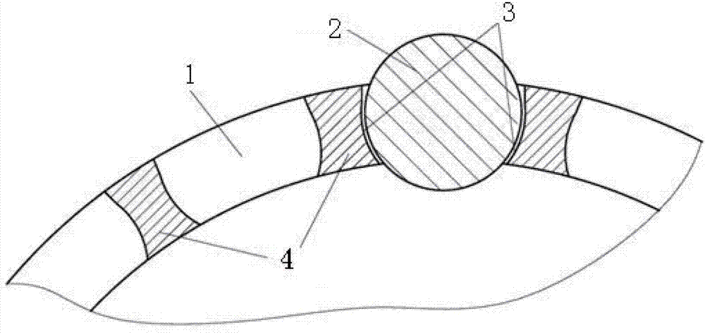
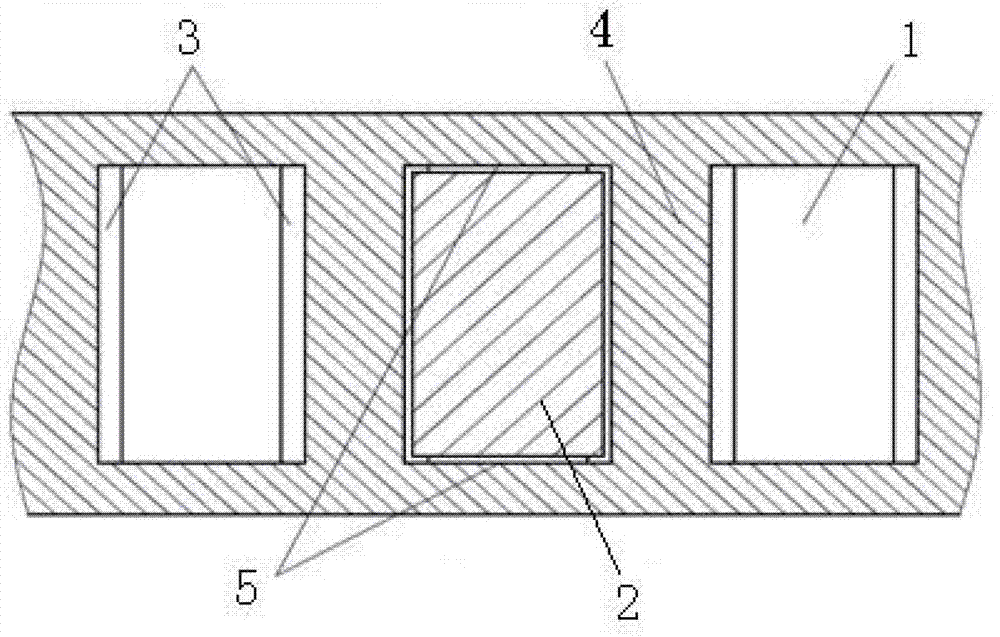
[0033] like figure 1 , figure 2 As shown, the bearing cage of the traction motor of a locomotive mainly includes a cage pocket 1, a cylindrical roller 2 and a cage cross rib 4, wherein the cage pocket arc surface 3 is between the cylindrical roller 2 and the cage cross rib 4 , the cage pocket arc surface 3 is the main worn surface of the cage; between the upper and lower axial ends of the cylindrical roller 2 and the cage transverse rib 4 is the cage pocket side wall 5, because the cage The two side walls of the cylinder will be worn due to the axial movement of the cylindrical roller 2, but th...


PUM


Abstract

The invention provides a method for judging whether an abrasion of a bearing retainer of a locomotive traction motor fails or not. The method comprises the steps of S1, establishing a copper alloy retainer three-dimensional model through computer-aided design (CAD); S2, correcting the calculated weight of the three-dimensional model in the CAD to be equal to the actual weight; S3, according to a selected bearing model, setting the unilateral maximum permissible abrasion depth of an arc surface of a pocket of the copper alloy retainer, and obtaining the maximum mass m1 of the copper alloy retainer, which is abraded, through the CAD; S4, calculating the mass mCu of Cu elements in the maximum mass m1; S5, calculating the maximum content ppm(Cu)(max) of the Cu elements in lubricating oil; and S6, measuring a ppm value ppm(Cu)' of the Cu elements contained in the lubricating oil to be monitored in a locomotive, and comparing the ppm(Cu)' with the ppm(Cu)(max), wherein if the ppm(Cu)' >= the ppm(Cu)(max), the abrasion of the retainer fails and can not be used any longer, and if the ppm(Cu)' < the ppm(Cu)(max), the abrasion of the retainer does not fail. By the aid of the judging method, a scientific and reliable judgment foundation is provided to monitor whether the abrasion of the retainer fails or not, so that erroneous judgments are reduced.

Description

technical field [0001] The invention relates to the technical field of locomotive traction motors, in particular to a method for judging whether a bearing cage of a locomotive traction motor is worn out or not. Background technique [0002] At present, in the daily operation of the locomotive, due to the wear and tear of the bearing cage of the traction motor, the "slip" phenomenon occurs in the rolling between the cylindrical roller and the inner and outer rings of the bearing, which in turn causes the bearing to fail when it is loaded, and ultimately affects the safety of the locomotive. run. [0003] In the prior art, in order to monitor whether the wear of the bearing cage of the traction motor is invalid, or to completely disassemble the cage from the locomotive, and analyze the worn part to judge the wear state of the cage, this method is time-consuming and laborious. The implementation cost is high, and in the daily operation and maintenance of the locomotive, it is ...

Claims


Application Information

Patent Timeline
Patent Type & Authority Patents(China)
IPC IPC(8): G01M13/04
Inventor 杨镭李训虎言宏武
Owner CSR CHENGDU
Why Eureka
Try Eureka