Workpiece platform position error measurement and pre-compensation method

A workpiece table and error technology is applied in the field of measuring and pre-compensating the position error of the workpiece table. , the result is the real effect

Active Publication Date: 2013-09-11
SHANGHAI MICRO ELECTRONICS EQUIP (GRP) CO LTD
View PDF10 Cites 7 Cited by
  • Summary
  • Abstract
  • Description
  • Claims
  • Application Information

AI Technical Summary

Problems solved by technology

[0003] Due to the defect of the measurement function, when the measurement position is located on the edge of the silicon wafer, etc., the measurement of the focus and leveling sensor will produce a large error due to the small reflective area
In addition, the focus and leveling sensor takes a certain amount of time to measure the position of the silicon wafer. Therefore, the above-mentioned real-time measurement of the height of the silicon wafer and closed-loop control will affect the processing speed during the exposure process, thereby affecting the production efficiency of the lithography machine.

Method used


Image

  • Workpiece platform position error measurement and pre-compensation method
  • Workpiece platform position error measurement and pre-compensation method
  • Workpiece platform position error measurement and pre-compensation method

Examples


Embodiment Construction

[0025] Specific embodiments of the present invention will be described in detail below in conjunction with the accompanying drawings.

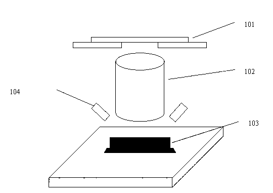
[0026] figure 2 Shown is a schematic diagram of the structure of a typical photolithography machine. A lithography machine usually includes a mask table 101, a lens 102, a workpiece table 103, and a focusing and leveling sensor 104. Usually, a marble table is used as a support table for the workpiece table and the mask table. In this case, since the surface of the marble table is very It is difficult to achieve absolute smoothness, and the height may change when the workpiece table and mask table are moved on it, which will introduce errors. image 3 Shown is a schematic diagram of the height error of the workpiece table. Assuming that the workpiece table 103 in the photolithography machine moves on the marble, the undulation of the marble surface will affect the height and inclination of the workpiece table. At the same time, because the ...


PUM


Abstract

The invention discloses a workpiece platform position error measurement and pre-compensation method comprising the following steps of: measuring at multiple positions, calculating the influence on the height and the incline of the workpiece platform caused by fluctuation of a support platform according to the measuring results, calculating the influence on the angle of inclination of the workpiece platform caused by the shape of a reflecting surface at the side face of the workpiece platform, and compensating the workpiece platform with the obtained error data according to the position of the workpiece.

Description

technical field [0001] The invention relates to the field of photolithography, in particular to a method for measuring and pre-compensating the position error of a workpiece table. Background technique [0002] The lithography machine exposes the silicon wafer placed on the workpiece table. During the exposure process, the upper surface of the silicon wafer is required to maintain a fixed distance from the projection lens to ensure that the upper surface of the silicon wafer is always in the best focal plane of the lens. For this reason, as described in U.S. Patent No. 6,172,757 B1, a focusing and leveling sensor is generally designed in a lithography machine. The position of the sensor and the projection lens is fixed, and the detection method of optical reflection on the silicon wafer is used to monitor the height of the silicon wafer in real time. Closed-loop control, so as to ensure that the exposed silicon surface does not go out of focus. [0003] Due to the defect of...

Claims


Application Information

Patent Timeline
IPC IPC(8): G03F7/20G03F9/00G01B11/02G01B11/26
Inventor 林彬段立峰
Owner SHANGHAI MICRO ELECTRONICS EQUIP (GRP) CO LTD
Why Eureka
Try Eureka