Resonance derivative ring

A technology of derivative ring and resonant ring, applied in electrical components, circuit devices, electromagnetic wave systems, etc., can solve the problems of low withstand voltage, monotonic coupling mode, limited energy distribution density, etc., to improve power, improve transmission power and efficiency, The effect of improving received power and efficiency

Inactive Publication Date: 2013-09-11
朱斯忠
View PDF3 Cites 6 Cited by
  • Summary
  • Abstract
  • Description
  • Claims
  • Application Information

AI Technical Summary

Problems solved by technology

[0003] In the existing patent "resonance derivative ring 201020523538.8", the structure of the resonance derivative ring is single, the coupling method is monotonous, the energy distribution density is limited, the withstand voltage is low, and the resonance amplitude is uncontrollable, etc. These problems have seriously affected its practical application. sex and flexibility

Method used


Image

  • Resonance derivative ring
  • Resonance derivative ring
  • Resonance derivative ring

Examples


example 1

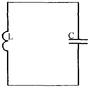
[0042] Example 1, the composition form of the resonance derivation ring.

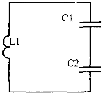
[0043] figure 1 Among them, an equivalent inductance L and an equivalent capacitance C are connected end to end to form a series LC resonant circuit, and the resonant frequency is the same as the operating frequency of the transmitting coil. The equivalent inductance L here includes: a single inductance; two and More than two inductances are formed in series, in parallel, or even in combination. The inductance includes air-core coils, coils wound on the skeleton and magnetic cores, such as Figure 2A and Figure 2B Inductor L1 in, and Figure 2C and Figure 2D The inductance L1 and the inductance L2; The equivalent capacitance C here includes: a single capacitance; two or more than two capacitances are connected in series, in parallel, or even in combination, such as Figures 2A-2D The equivalent capacitance C1 and the capacitance equivalent C2 in.

[0044] Commonly used resonance derivative rings ...

example 2

[0047] Example 2. The application of resonance derivative ring in AGV wireless charging.

[0048] AGV is the abbreviation of Automatic Guided Vehicle, which is the abbreviation of unmanned van. AGV is a kind of mobile industrial equipment. The power comes from the battery in the car. If it uses wired charging, it needs manual operation. Figure 3B It is the basic principle of wireless charging, in which the equivalent inductance L1 and the equivalent capacitance C1 are connected in series to form a resonance derivative ring, the receiving coil LR and the output capacitors CR1 and CR2 form a power output loop, and the transmitting coil LT and the transmitting capacitor CT form a transmitting loop; here The equivalent inductance L1 of the resonance derivative ring and the receiving coil LR are wound on the same magnetic core. The resonance derivative ring absorbs the magnetic energy from the transmitting circuit and converts it into electrical energy to generate resonance. The en...

example 3

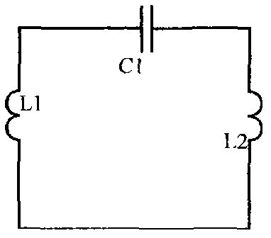
[0049] Example 3, the application of the resonance derivative ring in long-distance transmission.

[0050] attached Figure 3AAmong them, the transmission circuit composed of coil LT and capacitor CT is a current-type transmission circuit. When working in the resonant state, the total current of the circuit is at the minimum state, so the transmission power is also the minimum; from the equivalent capacitors C1 and C2, the equivalent Inductors L1 and L2 are connected in series to form a resonance-derived loop in the form of L-C-L-C, in which the equivalent inductance L1 and the transmitting coil LT are wound on the same magnetic core, so the resonance-derived loop can absorb the energy of the transmitting loop and transfer it to the equivalent Re-transmission in the inductor L2 increases the transmission power in magnitude.


PUM


Abstract

The invention provides a resonance derivative ring. The resonance derivative ring is a closed ring resonator formed by an equivalent inductor L and an equivalent capacitor C in a series connection mode, namely the two ends of the equivalent inductor L are respectively connected with two electrodes of the equivalent capacitor C to form an LC resonance same loop which has the functions of absorbing electric energy and then emitting the electric energy. The resonance derivative ring has various forming modes and various energy coupling modes, any two connecting points of the resonance derivative ring can output the electric energy, and the work of the resonance derivative ring is controllable. Various achieving modes of the resonance derivative ring are provided, the energy on the resonance derivative ring can be effectively controlled and output, the power and the efficiency of wireless power supply based on electromagnetic resonance are improved, and the distance of the wireless power supply based on the electromagnetic resonance is prolonged. The resonance derivative ring can be widely used for non-contact wireless power supply in industrial work, agricultural work or even daily work.

Description

technical field [0001] The present invention is an LC resonant ring for energy transmission between a transmitting coil and a receiving coil in electromagnetic resonance, which is called a resonance derivative ring. Background technique [0002] The resonance derivative ring has the function of relay or bridge in electromagnetic resonance. It can not only enhance the transmission power of electromagnetic resonance, increase the distance of electromagnetic resonance, but also change the direction of electromagnetic resonance transmission. [0003] In the existing patent "resonance derivative ring 201020523538.8", the structure of the resonance derivative ring is single, the coupling method is monotonous, the energy distribution density is limited, the withstand voltage is low, and the resonance amplitude is uncontrollable, etc. These problems have seriously affected its practical application. sex and flexibility. [0004] The present invention comprehensively solves the abov...

Claims


Application Information

Patent Timeline
Patent Type & Authority Applications(China)
IPC IPC(8): H02J17/00H02J50/12
Inventor 朱斯忠
Owner 朱斯忠
Why Eureka
Try Eureka