
Bearingless switched reluctance motor and control method thereof

A switched reluctance motor and bearingless technology, which is applied in the direction of AC motor control, electronic commutation motor control, control system, etc., can solve winding current tracking, restrict bearingless switched reluctance motor suspension and operation performance is difficult to improve, current Unable to solve problems, to achieve the effect of optimized design and high-speed adaptability

Inactive Publication Date: 2013-09-11
NANJING UNIV OF POSTS & TELECOMM
View PDF1 Cites 30 Cited by
  • Summary
  • Abstract
  • Description
  • Claims
  • Application Information

AI Technical Summary

Problems solved by technology

[0003] There is a complex coupling relationship between torque and levitation force, and it is difficult to realize the complete decoupling of the two in the control strategy and mathematical model, which is an important factor restricting the improvement of the levitation and operation performance of the bearingless switched reluctance motor
In addition, when the levitation force is controlled, it is necessary to control the winding current by chopping, and when running at high speed, the surge of the counter electromotive force makes it impossible to track and control the winding current, that is, the current cannot be chopped, which seriously affects the Exerting High Speed ​​Performance of Bearing Switched Reluctance Motor

Method used


Image

  • Bearingless switched reluctance motor and control method thereof
  • Bearingless switched reluctance motor and control method thereof
  • Bearingless switched reluctance motor and control method thereof

Examples


Embodiment Construction

[0018] In the following, a bearingless switched reluctance motor and its control method proposed by the present invention will be further described in detail with reference to the accompanying drawings.

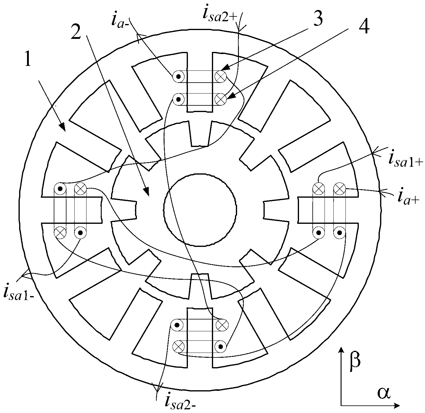
[0019] Such as figure 1 Shown is a schematic diagram of the structure of a bearingless switched reluctance motor of the present invention and the connection of the A-phase winding. The motor is a three-phase 12 / 8-pole dual-winding bearingless switched reluctance motor, where 1 is the stator and 2 is the rotor , 3 is the torque winding, 4 is the suspension winding. The winding connection method is: the winding forms of the torque winding and the suspension winding are concentrated windings, and each stator tooth is wound with a torque winding and a suspension winding; 4 torque windings on the stator teeth separated by 90° The forward connection is a phase, and the two suspension windings in each phase are connected in reverse series in the α-axis direction and the β-axis directio...


PUM


Abstract

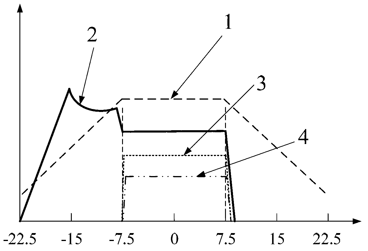
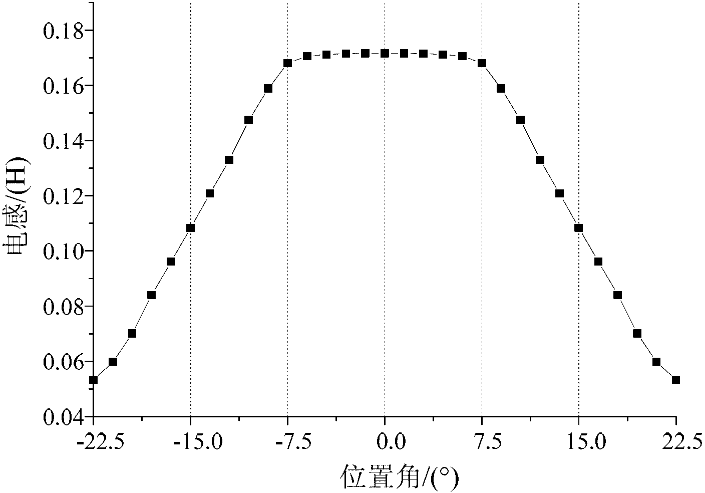
The invention provides a bearingless switched reluctance motor and a control method thereof. The difference between a rotor pole arc angle and a stator pole arc angle of the motor is 15 degrees, current of torque windings and suspension windings are controlled to generate suspension force, the current of the torque windings is controlled so as to generate torque, and current of the torque winding of each phase and turn-on and turn-off angle of the torque winding are regulated to achieve a speed closed loop; radial displacement of a rotor is detection, and radial force needed for rotor suspension is outputted via PID (proportion integration differentiation) regulators, so that closed-loop control of radial displacement of the rotor is achieved. The suspension windings are only excited and conducted in a maximum-inductance flat-top area and do not generate torque, so that the torque and the suspension force can be decoupled in control, and current magnitude of the torque windings and the suspension windings is optimized to make copper loss of the windings to be minimum; in addition, counter potential of the suspension windings and the torque windings is zero in the maximum-inductance flat-top area, and high-speed suspended running of the bearingless switched reluctance motor is benefitted so as to give full play to high-speed adaptability of the switched reluctance motor.

Description

Technical field [0001] The invention belongs to the technical field of automatic control, and particularly relates to a bearingless switched reluctance motor and a control method thereof. Background technique [0002] Bearingless switched reluctance motors are divided into dual winding structure and single winding structure. The dual-winding bearingless switched reluctance motor is the suspension winding that generates the suspension force and the winding of the switched reluctance motor are stacked together on the stator of the motor, and the motor has the ability of rotation and self-suspension by controlling the two sets of winding currents. High-speed operation of the motor. The single-winding bearingless switched reluctance motor has the ability of both rotation and self-suspension by independently controlling the current of each winding. [0003] There is a complex coupling relationship between torque and levitation force, and it is difficult to achieve complete decoupling ...

Claims


Application Information

Patent Timeline
IPC IPC(8): H02K19/10H02P6/00H02P25/08
Inventor 杨艳刘泽远曹鑫邓智泉
Owner NANJING UNIV OF POSTS & TELECOMM
Learn More