Optical fiber drawing method for large-diameter optical fiber preform rod

An optical fiber preform, large-diameter technology, applied in glass fiber drawing devices, manufacturing tools, glass manufacturing equipment, etc., can solve the problems of fiber strength drop, air leakage, drawing furnace oxidation, etc., and achieve the effect of not easy adhesion

Active Publication Date: 2013-09-18
JIANGSU FASTEN PHOTONICS
View PDF7 Cites 31 Cited by
  • Summary
  • Abstract
  • Description
  • Claims
  • Application Information

AI Technical Summary

Problems solved by technology

There is also the design of directly sealing the optical fiber preform and the drawing furnace mouth through the graphite soft felt; the invention patent 200810134932. Sealing, however, in these designs, because the drawing furnace adopts a downward airflow direction, the sealing material used at the furnace mouth is under the action of high temperature and friction, causing some graphite soft felt carbon powder to enter the drawing furnace, which will cause the strength of the optical fiber to decrease ; In the structure of the two-unit graphite sheet seal in the invention patent 200810134932.x, the elasticity of the graphite sheet is very small at high temperature, ...

Method used


Image

  • Optical fiber drawing method for large-diameter optical fiber preform rod
  • Optical fiber drawing method for large-diameter optical fiber preform rod
  • Optical fiber drawing method for large-diameter optical fiber preform rod

Examples


Embodiment Construction

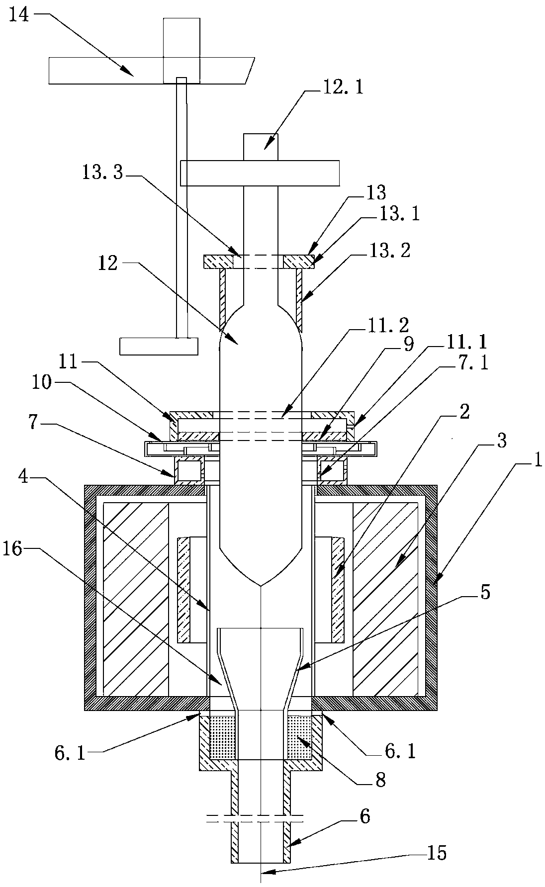
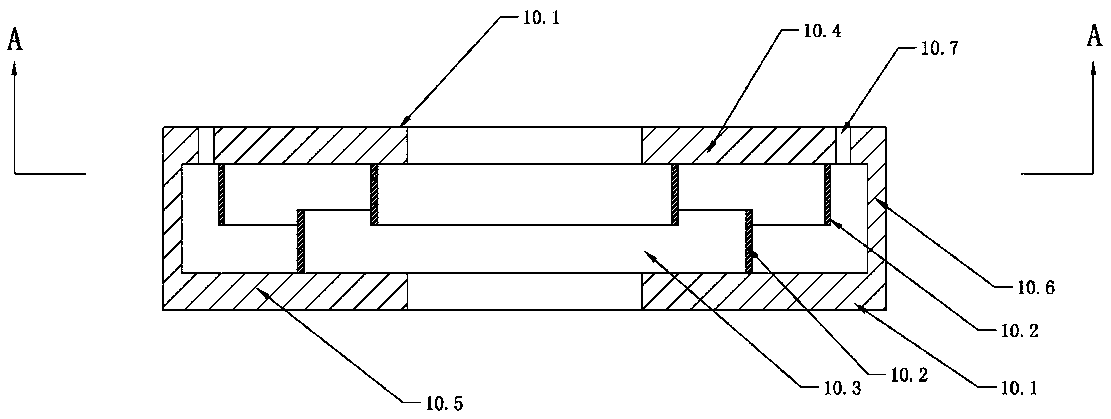
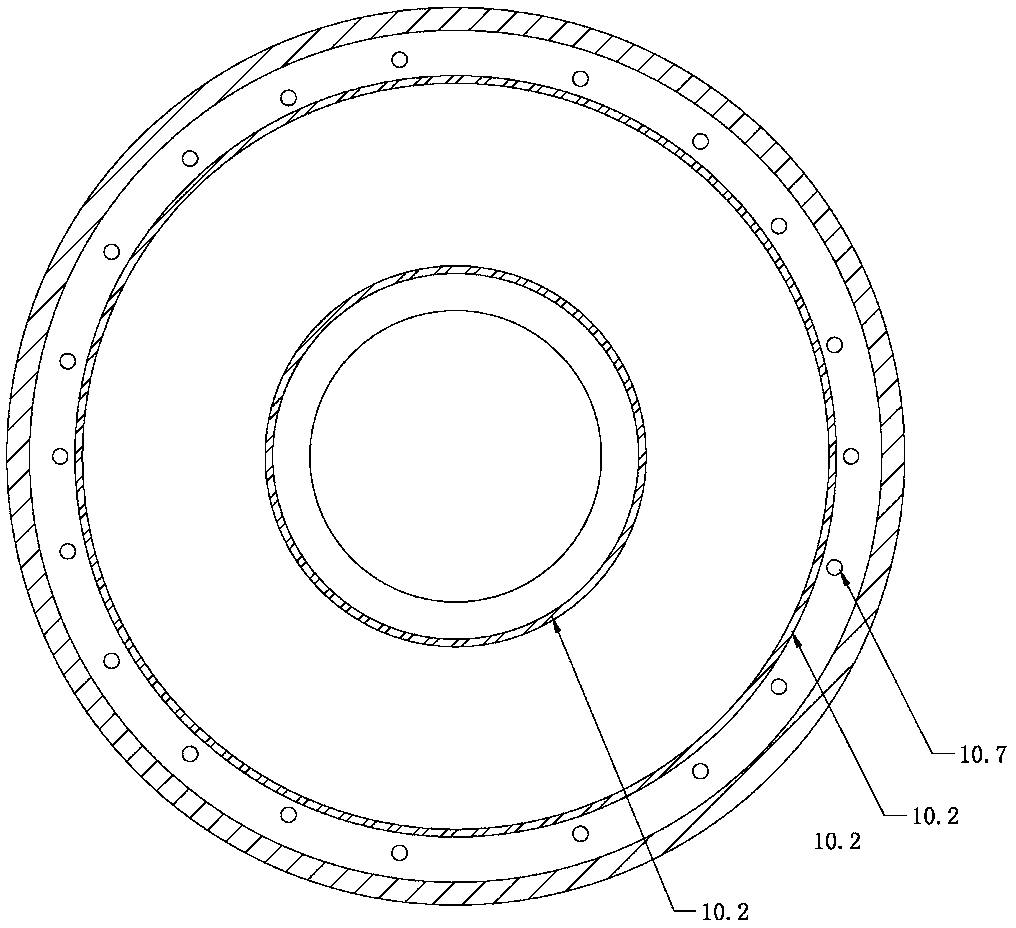
[0013] Such as figure 1 , figure 2 and image 3 As shown, the optical fiber drawing furnace includes a furnace body 1, a heating element 2, an insulating body 3, a middle casing 4, a guide tube 5, an extension tube 6, a furnace top gas plate 7, a spacer ring 8, an elastic graphite ring piece 9, a guide tube Air disk 10 and air seal cover 11; air guide disk 10 includes a hollow ring disk 10.1 and several ring pieces 10.2, the inner ring of the hollow ring disk 10.1 is an open opening 10.3, and several ring pieces 10.2 are on the upper inner wall 10.4 of the hollow ring disk , lower inner wall 10.5 upper and lower adjacent staggered installation, on the upper inner wall 10.4 near the outer wall 10.6 of the hollow ring disk 10.1 is provided with a circle of some air outlet holes 10.7; 10.7 Vertically upward, the elastic graphite ring piece 9 is installed on the hollow ring disk 10.1 inside the air outlet 10.7; the spacer ring 8 is arranged between the flow guide tube 5 and the...


PUM


Abstract

The invention relates to an optical fiber drawing method for a large-diameter optical fiber preform rod. The method comprises the following steps: continuously moving the large-diameter optical fiber preform rod downwards to enter an optical fiber drawing furnace through a lifter, heating and drawing to form a finished optical fiber, inputting protective gas into the furnace body through an extension pipe at the furnace bottom, allowing the protective gas to flow upwards, allowing the gas to flow out of a gas outlet of a gas guide disc, and allowing the protective gas input by the gas guide disc and a gas sealing cover to flow out of the gas outlet of the gas guide disc. The method has the advantage that the large-diameter optical fiber preform rod can be drawn to form the optical fiber with stable quality.

Description

technical field [0001] The invention relates to an optical fiber drawing method, in particular to an optical fiber drawing method for a large-diameter optical fiber preform. Background technique [0002] At present, the drawing method of optical fiber is to continuously move the lower end of the quartz glass rod of the optical fiber preform into the fiber drawing furnace and draw it into an optical fiber after being heated. A draft pipe, an extension pipe and a furnace top gas tray; the upper and lower walls of the furnace body are respectively provided with an upper drawing hole and a lower drawing hole, and the middle casing is arranged in the furnace body through the upper drawing hole and the lower drawing hole, and the heat preservation The body is arranged in the furnace body, the heating element is arranged in the furnace body between the middle casing and the heat preservation body, the top gas plate is set on the upper drawing hole, one end of the extension pipe is ...

Claims


Application Information

Patent Timeline
IPC IPC(8): C03B37/029
CPCC03B37/029C03B2205/56C03B2205/63C03B2205/81C03B2205/82
Inventor 俞华黄本华周震华陈强洪留明
Owner JIANGSU FASTEN PHOTONICS
Why Eureka
Try Eureka