Eureka AIR delivers breakthrough ideas for toughest innovation challenges, trusted by R&D personnel around the world.

Double-flow rotor spinning machine

A rotor spinning machine, dual air flow technology, applied in textiles, papermaking, spinneret assemblies, etc., can solve the problems of low end breakage rate, hard hand feeling, high maintenance requirements, and achieve the effect of improving labor productivity

Inactive Publication Date: 2013-09-18
HEBEI JINFANG MACHINERY MFG
View PDF8 Cites 3 Cited by
  • Summary
  • Abstract
  • Description
  • Claims
  • Application Information

AI Technical Summary

Problems solved by technology

The negative pressure airflow required for spinning on the self-exhausting rotor spinning machine is generated by the rotation of the perforated rotor, and the airflow flows from the mouth of the rotor to the bottom of the cup. Although the diameter of the rotor is large and the structure is simple, the negative pressure inside the rotor The pressure level has a lot to do with the speed of the rotor speed, so a certain rotor speed must be ensured; dust and impurities are easy to accumulate in the condensate groove of the rotor; lint is easy to accumulate around the exhaust hole of the rotor, thereby reducing the Negative pressure
The negative pressure airflow required for spinning on the air suction rotor spinning machine is generated by the suction of the centrifugal fan, and the airflow flows from the bottom of the cup to the mouth of the cup. Due to the different structures of the two rotors, the direction of the airflow in the rotor is also different. The styles are quite different. Although the negative pressure is stable and consistent, it can avoid dust and impurities from accumulating in the condensate tank, and the end-break rate is low, but the yarn produced has high twist, hard hand feeling, high maintenance requirements, and low impurity content in raw materials.

Method used


Image

  • Double-flow rotor spinning machine
  • Double-flow rotor spinning machine

Examples


Embodiment Construction

[0015] The principles and features of the present invention will be described below with reference to the accompanying drawings. The examples cited are only used to explain the present invention, and are not used to limit the scope of the present invention.

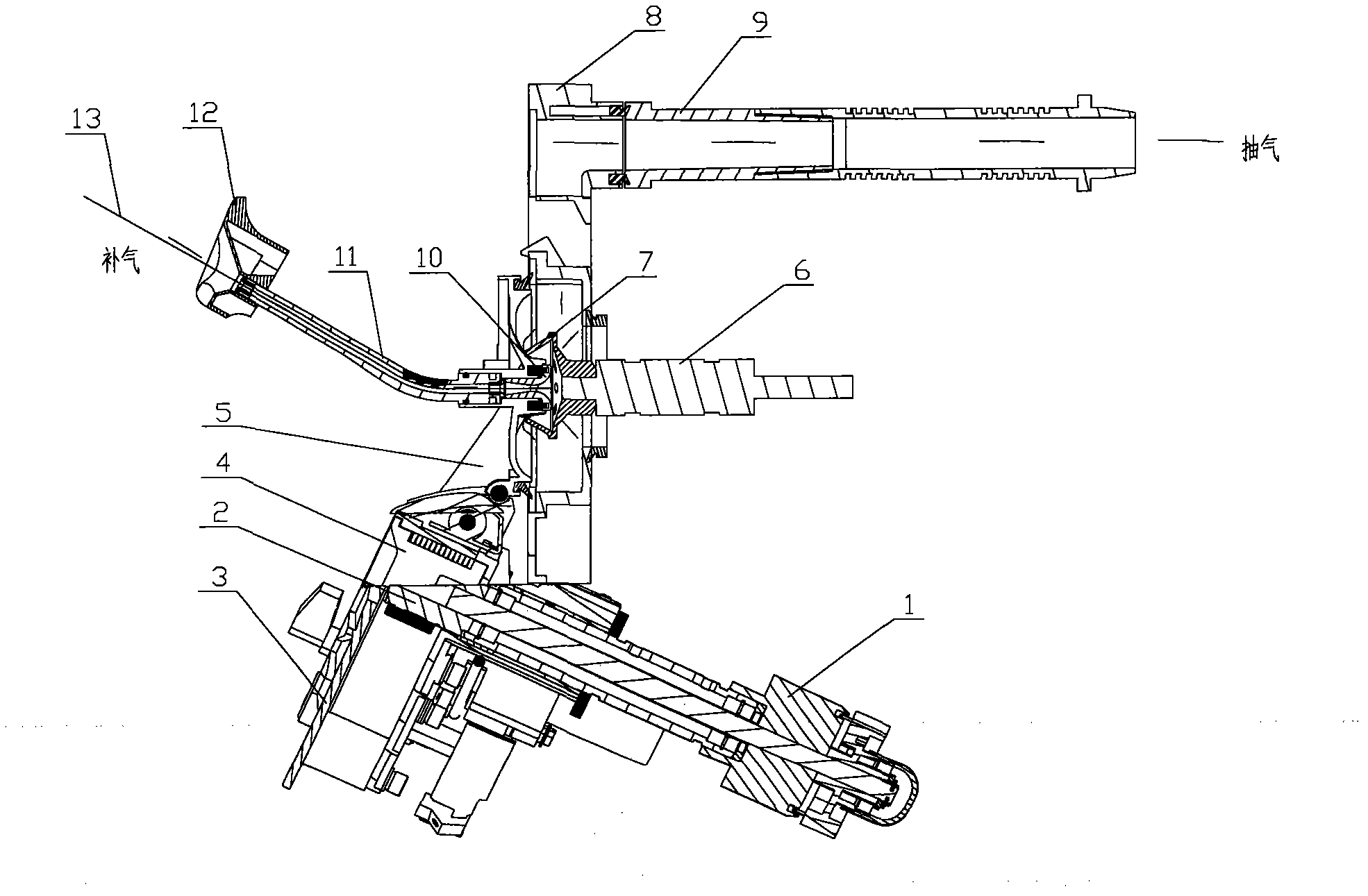
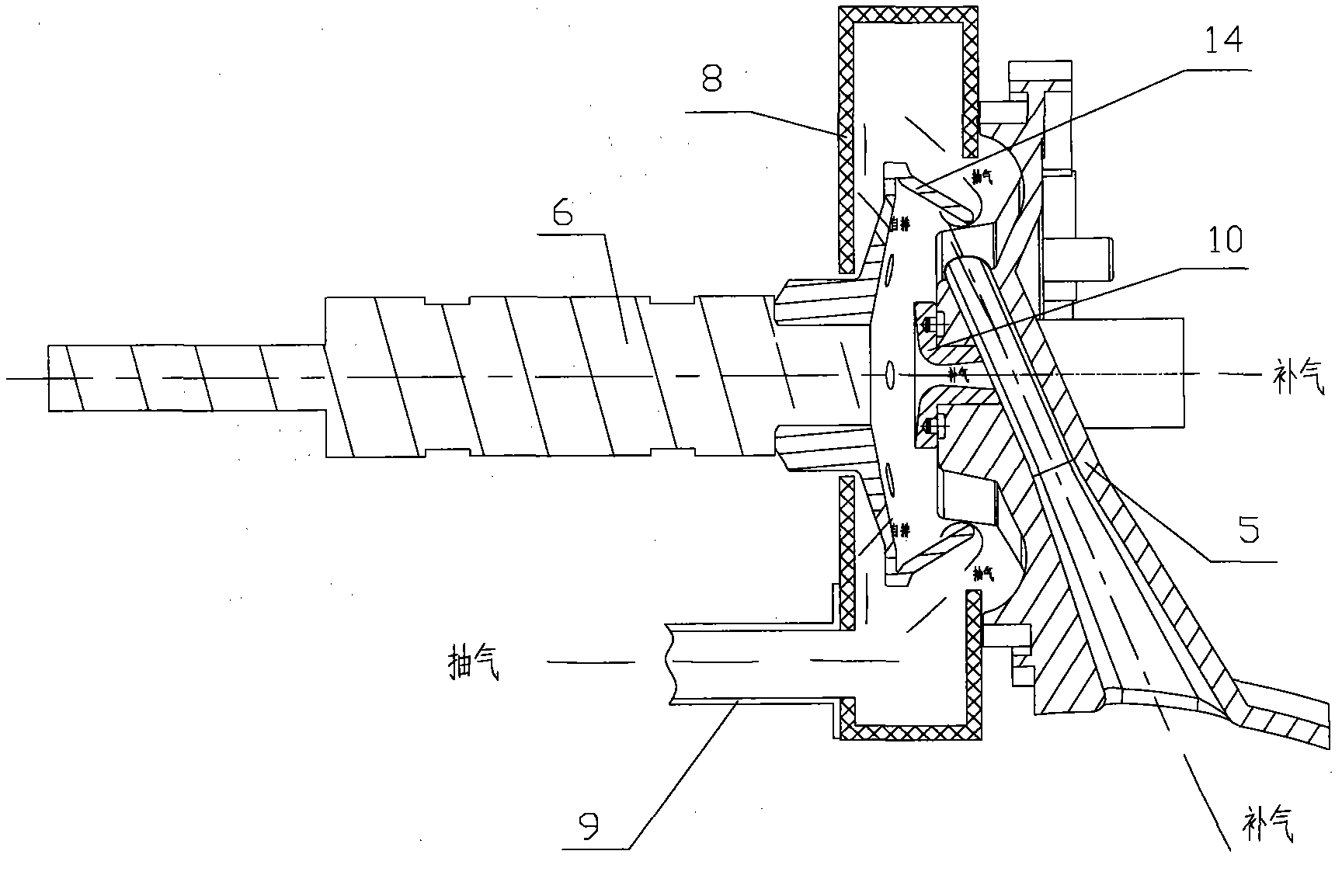
[0016] Such as figure 1 with 2 As shown, the described dual-air rotor spinning machine is characterized by comprising a rotor cavity 8, a shunt cavity assembly 3 and a feeding roller assembly 1 which are connected to the rotor cavity 8. The cavity 8 is provided with a rotor cup 7 with holes, the rotor cup 7 with holes is mounted on the rotor cup bearing 6 on the rotor cup cavity 8, and the feeding roller assembly 1 is provided with a feeding shaft 2 for feeding The shaft 2 and the shunt roller 4 in the shunt cavity assembly 3 are installed in parallel on the shunt cavity assembly 3. The shunt cavity assembly 3 is inlaid with a fiber transmission channel 5, and the upper end of the fiber transmission channel 5 is connected to ...


PUM


Abstract

The invention relates to the technical field of spinning equipment, in particular to a double-flow rotor spinning machine. The double-flow rotor spinning machine is characterized by comprising a rotor cavity, wherein a flow dividing cavity assembly and a feeding roller assembly are connected with the rotor cavity; the rotor cavity is provided with a rotor with a hole; the rotor with the hole is arranged on a rotor bearing on the rotor cavity; the feeding roller assembly is provided with a feeding shaft; the feeding shaft and a flow dividing roll in the flow dividing cavity assembly are arranged in parallel on the flow dividing cavity assembly; a fiber conveying passage is embedded on the flow dividing cavity assembly; the upper end of the fiber conveying passage and the rotor with the hole are correspondingly provided with a navel and a doffing tube; the upper part of the rotor cavity is fixedly connected with a process air duct. The double-flow rotor spinning machine utilizes the advantages of self-exhausting and air extracting spinning machines and avoids the defects of the self-exhausting and air extracting spinning machines; by bidirectional influence and interference of double negative pressure gas flows on fibers in the rotor, yarns with a unique style are formed; differentiated production is implemented; different consumer groups are met. Energy is saved, consumption is reduced and labor productivity is improved.

Description

Technical field [0001] The present invention relates to the technical field of spinning equipment, in particular to a double-air rotor spinning machine. Background technique [0002] Rotor spinning is one of the new spinning technologies. Compared with traditional spinning technology, it has the characteristics of short process, high efficiency, high quality, and labor saving. It is the focus of spinning technology transformation in my country in the future. The rotor spinning machines in the prior art are divided into two types: self-exhaust type and suction type. The negative pressure airflow required for spinning by self-venting rotor spinning machine is generated by the rotation of the perforated rotor. The airflow flows from the mouth of the rotor to the bottom of the cup. Although the rotor has a large diameter and simple structure, the negative pressure inside the rotor The pressure level has a lot to do with the speed of the rotor speed, so a certain rotor speed must be ...

Claims


Application Information

Patent Timeline
IPC IPC(8): D01D4/08
Inventor 陈明郜志军卢学俊
Owner HEBEI JINFANG MACHINERY MFG
Why Eureka
Eureka Blog
Learn More