Backlight module and television
A backlight module and backplane technology, applied in the field of televisions, can solve the problems of light energy loss, increase the use of optical film, reduce production efficiency, etc. Effect
- Summary
- Abstract
- Description
- Claims
- Application Information
AI Technical Summary
Problems solved by technology
Method used
Image

Examples
Embodiment 1
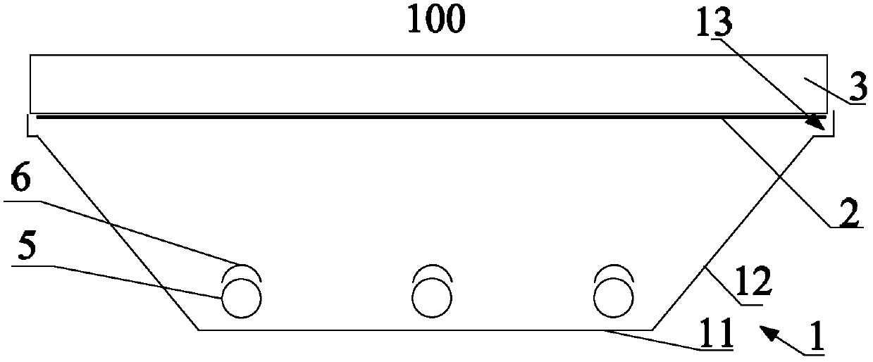
[0025] Such as figure 1 As shown, the present invention provides a backlight module 100, including a liquid crystal panel 3 installed in sequence, an optical film 2 fixedly arranged on the polarizing surface under the liquid crystal panel 3, supporting the liquid crystal panel 3 and the The back plate 1 of the optical film 2 and the reflection sheet attached to the inner wall of the back plate 1, the open end of the back plate 1 is provided with a step groove 13, and the liquid crystal panel panel is provided with the optical film Installed in the step groove 13.
[0026] The present invention adopts a new type of backlight module, saves the diffusion plate in the existing backlight module, and directly installs the optical film on the liquid crystal panel, and the liquid crystal panel and the optical film are taken as a whole by the opening end of the back plate support. After removing the diffusion plate, the loss of light energy caused by the diffusion of the light source...
Embodiment 2
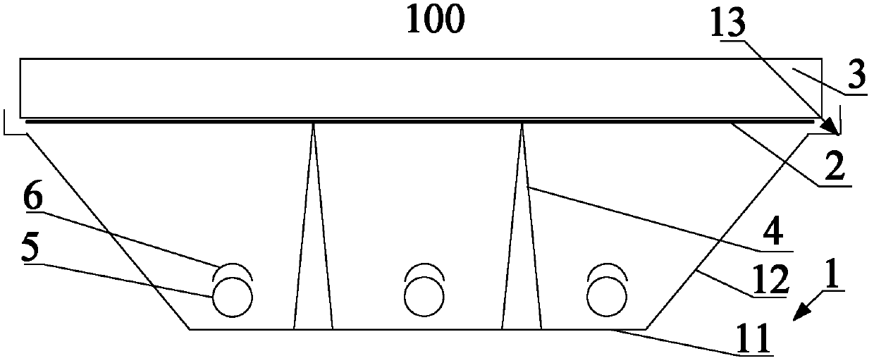
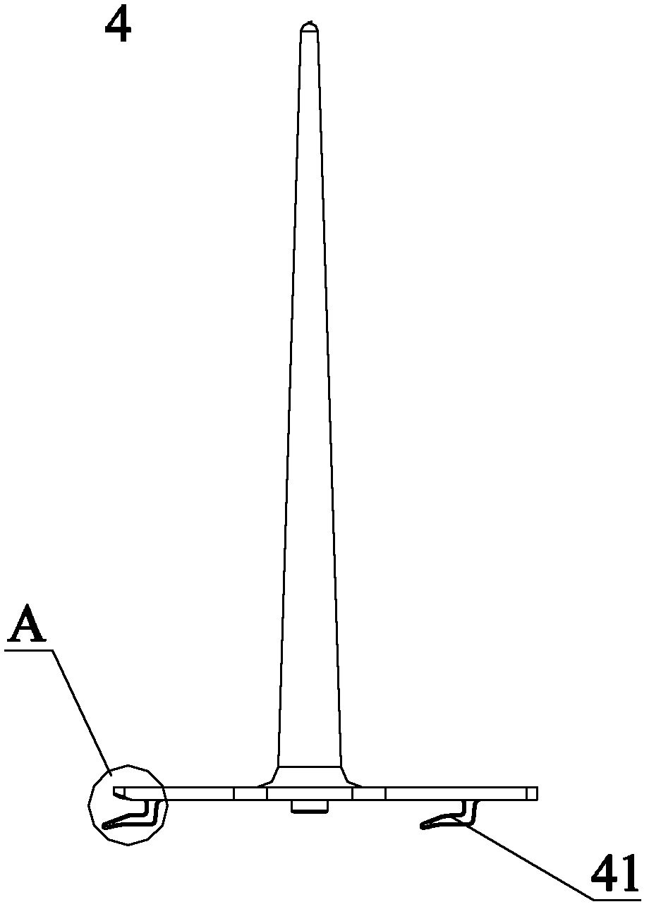
[0042] Such as figure 2 , image 3 and Figure 4 As shown, the present invention provides a backlight module 100, including a liquid crystal panel 3 installed in sequence, an optical film 2 fixedly arranged on the polarizing surface under the liquid crystal panel 3, supporting the liquid crystal panel 3 and the The back plate 1 of the optical film 2 and the reflection sheet attached to the inner wall of the back plate 1, the open end of the back plate 1 is provided with a step groove 13, and the liquid crystal panel panel is provided with the optical film Installed in the step groove 13.
[0043] The present invention adopts a new type of backlight module, saves the diffusion plate in the existing backlight module, and directly installs the optical film on the liquid crystal panel, and the liquid crystal panel and the optical film are taken as a whole by the opening end of the back plate support. After removing the diffusion plate, the loss of light energy caused by the d...
PUM
 Abstract
Description
Claims
Application Information
 - R&D
- Intellectual Property
- Life Sciences
- Materials
- Tech Scout
- Unparalleled Data Quality
- Higher Quality Content
- 60% Fewer Hallucinations
Browse by: Latest US Patents, China's latest patents, Technical Efficacy Thesaurus, Application Domain, Technology Topic, Popular Technical Reports.
© 2025 PatSnap. All rights reserved.Legal|Privacy policy|Modern Slavery Act Transparency Statement|Sitemap|About US| Contact US: help@patsnap.com