
Forced-vibration damping pendulum

A forced vibration, single pendulum technology, applied in the field of forced vibration damping single pendulum, can solve the problems of limited application, single experimental function of the instrument, unadjustable vibration frequency, etc., to reduce costs, expand the scope of use, and achieve intuitive research Effect

Inactive Publication Date: 2013-09-18
NANJING INST OF TECH
View PDF8 Cites 7 Cited by
  • Summary
  • Abstract
  • Description
  • Claims
  • Application Information

AI Technical Summary

Problems solved by technology

The above-mentioned physical experimental instruments for studying forced vibration are not adjustable due to the inherent vibration frequency when the disc vibrates, and the observation of the angle of rotation is not intuitive enough, the experimental function of the instrument is relatively simple, and the structure of the experimental device is relatively complicated. Due to the influence of factors such as high cost and price, the popularization and application of this kind of physical experimental instruments for studying forced vibration is limited to a certain extent.

Method used


Image

  • Forced-vibration damping pendulum
  • Forced-vibration damping pendulum
  • Forced-vibration damping pendulum

Examples


Embodiment Construction

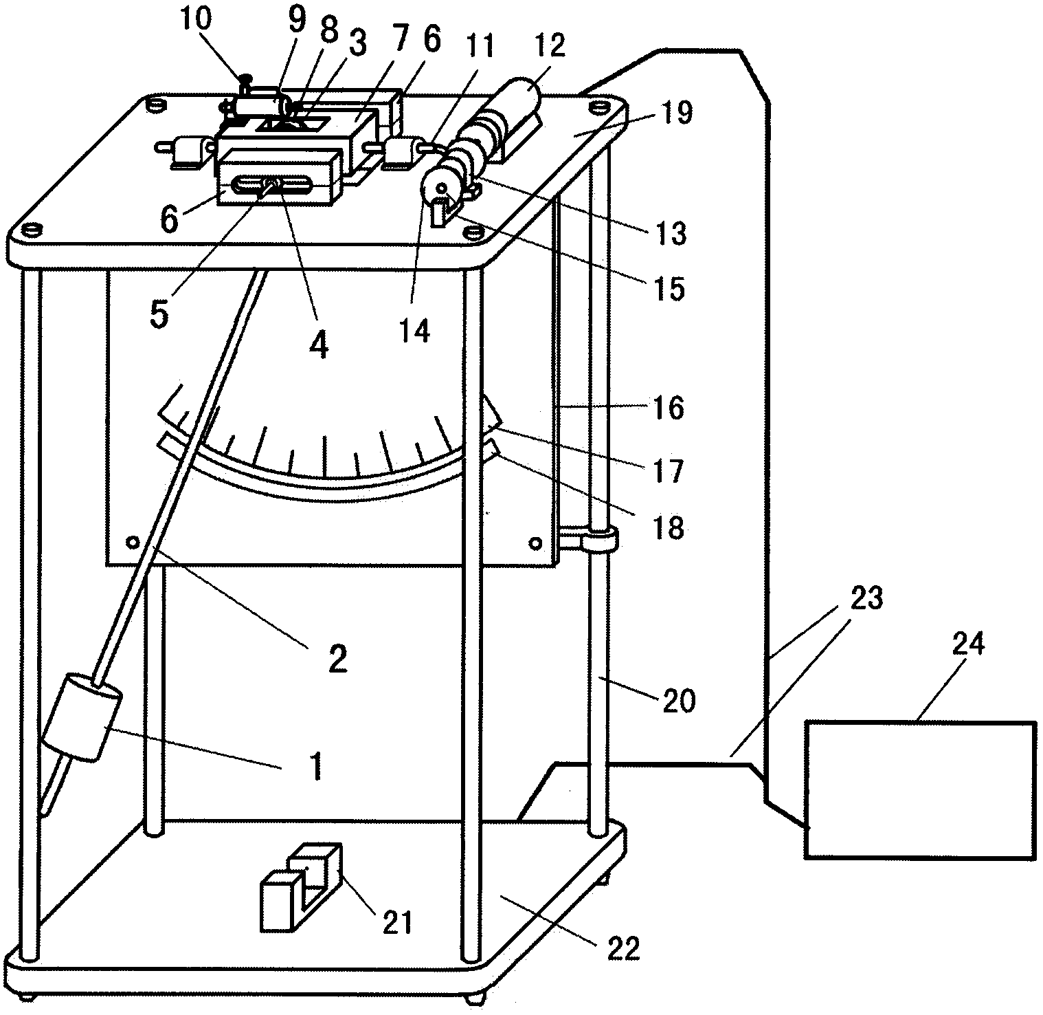
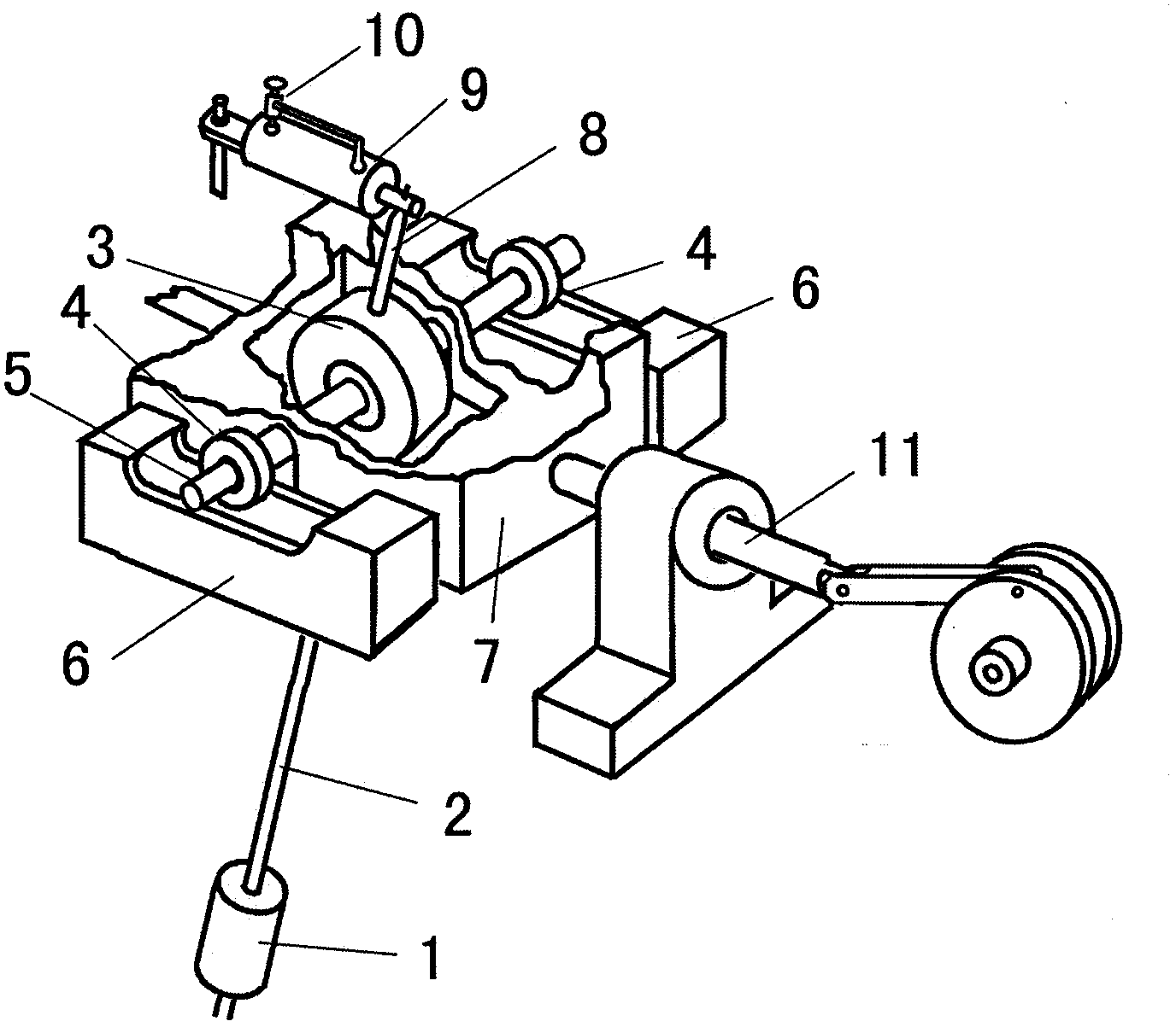
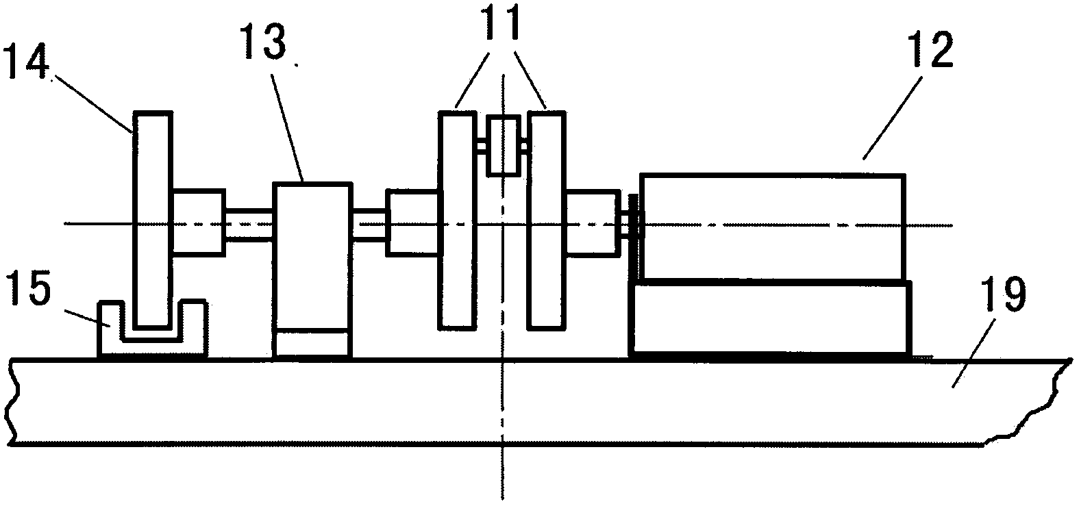
[0028] press figure 2 As shown in the structure diagram, the pendulum rod (2) of the single pendulum is connected with the center bearing and bearing sleeve (3), and the shift rod (8) is suspended on the movable shaft through the center bearing and bearing sleeve (3). (5) Above, without being driven by external force, a single pendulum composed of two parts of a pendulum (1) and a pendulum rod (2) can swing freely around the movable shaft (5). The period of its free swing conforms to the vibration law of a simple pendulum. On the other hand, there are two small rolling bearings (4) at both ends of the movable shaft (5). The two small rolling bearings (4) are mounted on the bearing guide rails (6) on both sides, and the movable shaft (5) is damped by a damping box. (7) Driven by the bayonet below, the damping box (7) is connected with the crankshaft connecting rod system (11). An air damping cylinder (9) is installed on the upper part of the damping box (7). The shift rod (8) ...


PUM


Abstract

A damping pendulum serves as a study object of forced vibration, the pendulum which is composed of a pendulum rod which is made of a rigid thin rod and a pendulum bob is suspended on a moving rotating shaft through a central bearing and a bearing sleeve, a driving lever is fixed on the bearing sleeve which is connected with the pendulum rod of the pendulum, and the pendulum rod of the pendulum, the bearing sleeve and the driving lever are connected into a whole. The driving lever penetrates a piston rod lantern ring of an air damping cylinder which is installed above a damping box, and the driving lever drives a piston rod to move back and forth when the pendulum swings. The magnitude of the damping force exerted on the driving lever by the piston rod of the air damping cylinder can be changed by adjusting an air flow valve on the air damping cylinder. An adjustable-speed motor is connected with the damping box through a crankshaft connecting rod system, the moving rotating shaft is driven to conduct reciprocating linear motion in the horizontal direction through a clamping opening below the damping box, and the periodic compulsive force in the horizontal direction is provided for the moving rotating shaft, so that the pendulum obtains energy required for maintaining of the stable forced vibration state.

Description

Technical field [0001] The invention relates to an experimental instrument for mechanics in physics, in particular to a forced vibration damping simple pendulum for studying the physical laws of forced vibration. Background technique [0002] Some of the existing physical experimental instruments for studying forced vibration have a common feature that uses a disk that rotates on a fixed axis, so that it torsionally vibrates back and forth around the axis of the disk under the torque of a torsion spring. A periodic external moment is used to indirectly impose a forced moment on the disc with the help of another torsion spring, so as to achieve the purpose of forced torsional vibration of the disc. The aforementioned physical experimental instruments for studying forced vibration are not adjustable due to the inherent vibration frequency of the disc vibration, and the angle of rotation is not intuitive enough, the experimental functions of the instrument are relatively simple, and...

Claims


Application Information

Patent Timeline
Patent Type & Authority Applications(China)
IPC IPC(8): G09B23/10
Inventor 吴庆春钱仰德刘扬正
Owner NANJING INST OF TECH
Learn More