Switch magnetic chain motor with concealed salient pole

A technology of switching flux linkage and salient pole, applied in the direction of magnetic circuit rotating parts, magnetic circuit shape/style/structure, etc., can solve the problems of weak magnetic speed regulation performance, large cogging torque, etc., to reduce the cogging The effect of torque, low cost, strong and weak magnetic field expansion performance

Inactive Publication Date: 2015-04-08
SOUTHEAST UNIV
View PDF6 Cites 0 Cited by
  • Summary
  • Abstract
  • Description
  • Claims
  • Application Information

AI Technical Summary

Problems solved by technology

[0005]Technical problem: In view of the problems of poor field-weakening speed regulation performance and large cogging torque in the traditional double salient pole switching flux linkage motor, in order to improve the performance of the switching flux linkage motor performance, the present invention provides a switch flux linkage motor with strong field-weakening speed expansion performance, reduced cogging torque, improved start-up performance, and effectively reduced the implied salient pole of torque ripple during operation

Method used


Image

  • Switch magnetic chain motor with concealed salient pole
  • Switch magnetic chain motor with concealed salient pole
  • Switch magnetic chain motor with concealed salient pole

Examples


Embodiment Construction

[0024] The present invention will be further specifically described below in conjunction with the accompanying drawings and embodiments.

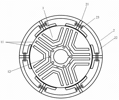
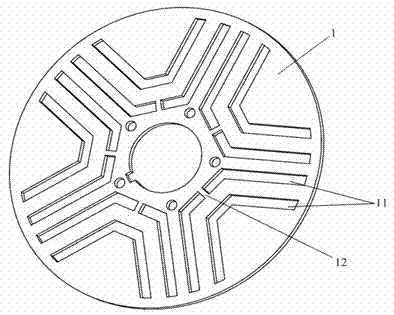
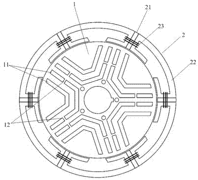
[0025] figure 1 , figure 2 The switched flux linkage motor with implied salient poles shown in the present invention includes a stator 2 with a salient pole structure and a rotor 1 with a smooth surface with implied salient poles. The stator 2 is composed of 6 U-shaped iron cores 22 , 6 rectangular permanent magnets 21 and 6 concentrated armature coils 23 . The rectangular permanent magnet 21 is embedded in the middle of the adjacent U-shaped iron cores 22 , and the concentrated armature coil 23 is wound on the teeth of the two adjacent U-shaped iron cores 22 . Adjacent rectangular permanent magnets 21 on the stator 2 are magnetized tangentially and in opposite directions. The A, B, C three-phase windings on the stator 2 are composed of six concentrated armature coils 23 connected, and two concentrated armature coils 23 of the same pha...


PUM


Abstract

The invention discloses a switch magnetic chain motor with a concealed salient pole. The switch magnetic chain motor comprises a stator of a salient pole structure and a rotor arranged on the inner side of the stator, 6n stator teeth positioned on the inner side are arranged on the stator, wherein n refers to a natural number larger than 0, a rectangular permanent magnet is arranged in each stator tooth, a centralized armature coil is wound in a tooth groove of each stator tooth, each rectangular permanent magnet is magnetized tangentially, two adjacent rectangular permanent magnets are opposite in magnetizing direction, and in-phase centralized armature coils are in serial or parallel connection to form a three-phase armature winding. No permanent magnet and winding is arranged on the rotor of the motor, so that the switch magnetic chain motor is simple and reliable in structure. A U-shaped magnetic insulating groove is formed in the rotor to form a non-magnetic path, and saturated magnetic bridges are formed on the U-shaped magnetic insulating groove close to the axis. Performance of the switch magnetic chain motor is improved by changing the structure of the rotor.

Description

technical field [0001] The invention belongs to the field of permanent magnet motors, and relates to a switched flux-linkage motor with implicit salient poles. Background technique [0002] Switched flux motors have received more and more attention since they were proposed. Its basic structure is similar to a switched reluctance motor, but with radial permanent magnets embedded in each stator tooth. The magnetic flux path generated by the permanent magnet changes with the change of the rotor position, which makes the magnetic flux of the stator winding turn chain alternate, which is essentially different from the switched reluctance motor with the permanent magnet embedded in the stator yoke. In the switched reluctance motor, the magnetic flux only changes in amplitude and has no polarity change with the rotor position, so the switched reluctance motor is a unipolar motor. In the switched flux linkage motor, the magnetic flux alternates with the rotor position, that is, bo...

Claims


Application Information

Patent Timeline
Patent Type & Authority Patents(China)
IPC IPC(8): H02K1/24
Inventor 林明耀李念付兴贺郝立
Owner SOUTHEAST UNIV
Why Eureka
Try Eureka