Syringe-microinjection-type infusion device based on shape memory alloy driven and method thereof

A technology of micro-injection and memory alloy, applied in flow monitors, devices introduced into the body, etc., can solve problems such as high cost, complex system, and unstable system, and achieve energy saving, small size, and high energy conversion efficiency.

Inactive Publication Date: 2013-09-25
ZHEJIANG UNIV
6 Cites 8 Cited by

AI-Extracted Technical Summary

Problems solved by technology

However, ordinary micro-motor infusion devices have proble...

Abstract

The invention discloses a syringe-microinjection-type infusion device based on shape memory alloy driven and a method thereof. A baffle, a first fixing plate and a second fixing plate are arranged on a base plate. Positioning holes are formed on a support plate and the baffle. Semi-cycle fixing grooves are formed on the first fixing plate and the second fixing plate. A stopping block is arranged in the middle of a push rod. Two sides of the stopping block are provided with a shape memory alloy spring and a reset spring. The end, with the reset spring mounted on, of the push rod penetrates the positioning hole on the baffle and contacts with a disposable syringe. The disposable syringe is placed in the semi-cycle fixing grooves of the first fixing plate and the second fixing plate, and is fixed on the first fixing plate and the second fixing plate through a first clamp and a second clamp. The end, with the shape memory alloy spring mounted on, of the push rod penetrates the positioning hole on the support plate which is fixed on the base plate through a bolt. The syringe-microinjection-type infusion device has the advantages that structure is simple, no noise is produced, size is small and the like, and is adaptable to micro-drug injection and the like.

Application Domain

Technology Topic

Image

  • Syringe-microinjection-type infusion device based on shape memory alloy driven and method thereof
  • Syringe-microinjection-type infusion device based on shape memory alloy driven and method thereof
  • Syringe-microinjection-type infusion device based on shape memory alloy driven and method thereof

Examples

  • Experimental program(1)

Example Embodiment

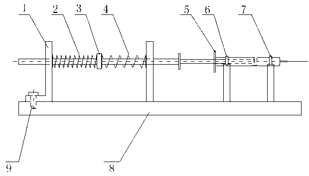
[0020] The working process of the syringe micro-injection infusion device driven by the shape memory alloy spring will be described in detail below with reference to the accompanying drawings.
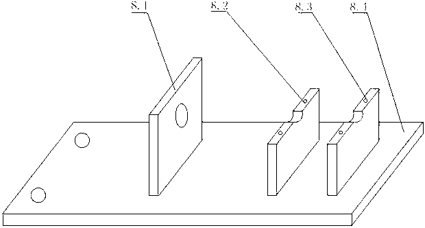
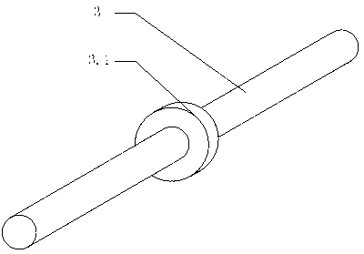
[0021] Such as Figure 1~4 As shown, a syringe microinjection infusion device driven by a shape memory alloy includes a support plate 1, a shape memory alloy spring 2, a push rod 3, a return spring 4, a disposable syringe 5, a first clamp 6, a second clamp 7, and Base 8; Base 8 includes baffle 8.1, first fixing plate 8.2, second fixing plate 8.3, bottom plate 8.4; bottom plate 8.4 is equipped with baffle 8.1, first fixing plate 8.2 and second fixing plate 8.3, support plate 1 and the baffle 8.1 are provided with positioning holes, the first fixed plate 8.2 and the second fixed plate 8.3 are provided with semi-circular fixed grooves, the push rod 3 is provided with a block 3.1 in the middle, and the two sides of the block 3.1 have shapes The memory alloy spring 2 and the return spring 4, the end of the push rod 3 where the return spring 4 is installed passes through the positioning hole of the baffle 8.1, and is in contact with the disposable syringe 5. The disposable syringe 5 is placed on the first fixing plate 8.2 and the second fixing In the semi-circular fixing groove on the plate 8.3, and fixed on the first fixing plate 8.2 and the second fixing plate 8.3 by the first clamp 6 and the second clamp 7, the end of the push rod 3 where the shape memory alloy spring 2 is installed penetrates Through the positioning holes of the support plate 1, the support plate 1 is fixed on the bottom plate 8.4 by bolts.
[0022] The shape memory alloy spring is made of nickel-titanium alloy material with a phase transition temperature of 55 to 75 degrees Celsius or 70 to 90 degrees Celsius, a spiral structure, an outer diameter of 7 mm to 15 mm, and a maximum stroke of 1 cm to 6 Between centimeters.
[0023] The said return spring adopts spring steel material and has a spiral structure, the outer diameter is between 7 mm and 15 mm, and the spring coefficient is between 0.2 N/mm and 3 N/mm.
[0024] The micro-injection method of the syringe driven by shape memory alloy is: the temperature of the shape memory alloy spring 2 rises under the action of a 1V to 5V electrical signal. When the temperature reaches above the phase transition temperature, the shape memory alloy spring 2 is controlled by the horse The state of stenosis transforms to the state of austenite, the hardness increases, and the length increases at the same time, which drives the push rod 3 to move in the direction of the disposable syringe 5 and squeeze the return spring 4 to start the injection process. After the injection process is over, the electrical signal stops In effect, the shape memory alloy spring 2 cools naturally, returning from the austenite state to the martensite state, and the hardness decreases, and the shape memory alloy spring 2 is restored to the initial position by the return spring 4 through the push rod 3. Depending on the capacity of the disposable syringe 5, the stroke of the shape memory alloy spring 2 is between 4 cm and 12 cm. By controlling the speed at which the shape memory alloy spring 2 bounces, the injection speed can be adjusted from 0.1 ml/h to 1500 ml/h between.
[0025] Such as Figure 5 Shown is a schematic diagram when the shape memory alloy spring 2 reaches the maximum stroke and the medicine in the disposable syringe 5 is completely extruded. At this time, the compression amount of the return spring 4 reaches the maximum value, and the electrical control signal output drops to zero at the same time.

PUM

PropertyMeasurementUnit
Phase transition temperature55.0 ~ 90.0°C
Outer diameter7.0 ~ 15.0mm
Spring rate0.2 ~ 3.0N/mm
tensileMPa
Particle sizePa
strength10

Description & Claims & Application Information

We can also present the details of the Description, Claims and Application information to help users get a comprehensive understanding of the technical details of the patent, such as background art, summary of invention, brief description of drawings, description of embodiments, and other original content. On the other hand, users can also determine the specific scope of protection of the technology through the list of claims; as well as understand the changes in the life cycle of the technology with the presentation of the patent timeline. Login to view more.

Similar technology patents

Gallium-arsenide-based multi-junction isotope micro cells

InactiveCN102097148AIncrease the open circuit voltageImprove energy conversion efficiencyRadiation electrical energyMicro cellBiology
Owner:BEIJING INSTITUTE OF TECHNOLOGYGY

Tritium-based nanotube isotope battery

InactiveCN107767983AImprove energy conversion efficiencyReduce chance of recombinationMaterial nanotechnologyRadiation electrical energyUnit volumeRadiation
Owner:大方元素(广东)科技有限公司

Brushless Motor and System Thereof

InactiveUS20170047834A1Risk be eliminate and substantially reduceImprove energy conversion efficiencyAssociation with control/drive circuitsSalient polesControl systemBrushless motors
Owner:FOSTER ASSETS CORPORATION

Classification and recommendation of technical efficacy words

  • Save energy
  • Improve energy conversion efficiency

High efficiency air conditioner condenser fan

InactiveUS20050281672A1Save energyDependable electric load reductionPropellersPump componentsPower savingAerospace engineering
Owner:UNIV OF CENT FLORIDA RES FOUND INC
Why Eureka
Try Eureka