

Gauge and method for measuring diameter of large-sized steel wire bearing rail
A large-size, steel wire technology, applied in the field of gauges for measuring the track diameter of large-size steel wire bearings, can solve the problems of easily scrapped parts, unreasonable structure, and low measurement efficiency, and achieve the effects of simple measurement, easy manufacturing, and high efficiency
- Summary
- Abstract
- Description
- Claims
- Application Information
AI Technical Summary
Problems solved by technology
Method used
Image

Examples
Embodiment Construction
[0038] The present invention will be described in further detail below in conjunction with the accompanying drawings.
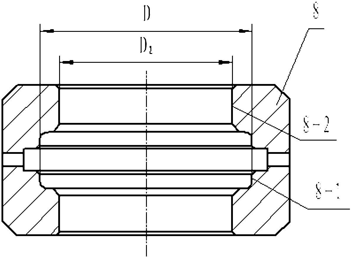
[0039] see figure 1 As shown, the measured part 8, because the diameter D of the large-size steel wire bearing track hole 8-1 is greater than 500mm, and there is a hole 8-2 smaller than D at both ends of the hole, so the general plug gauge cannot put the large-size steel wire In the hole of the bearing track, or the gauge cannot be taken out of the hole after being put into the measurement. Although the part 8 can be measured on a three-coordinate machine after the machining is completed, the measurement efficiency is too low, and it cannot be measured on the machine tool.
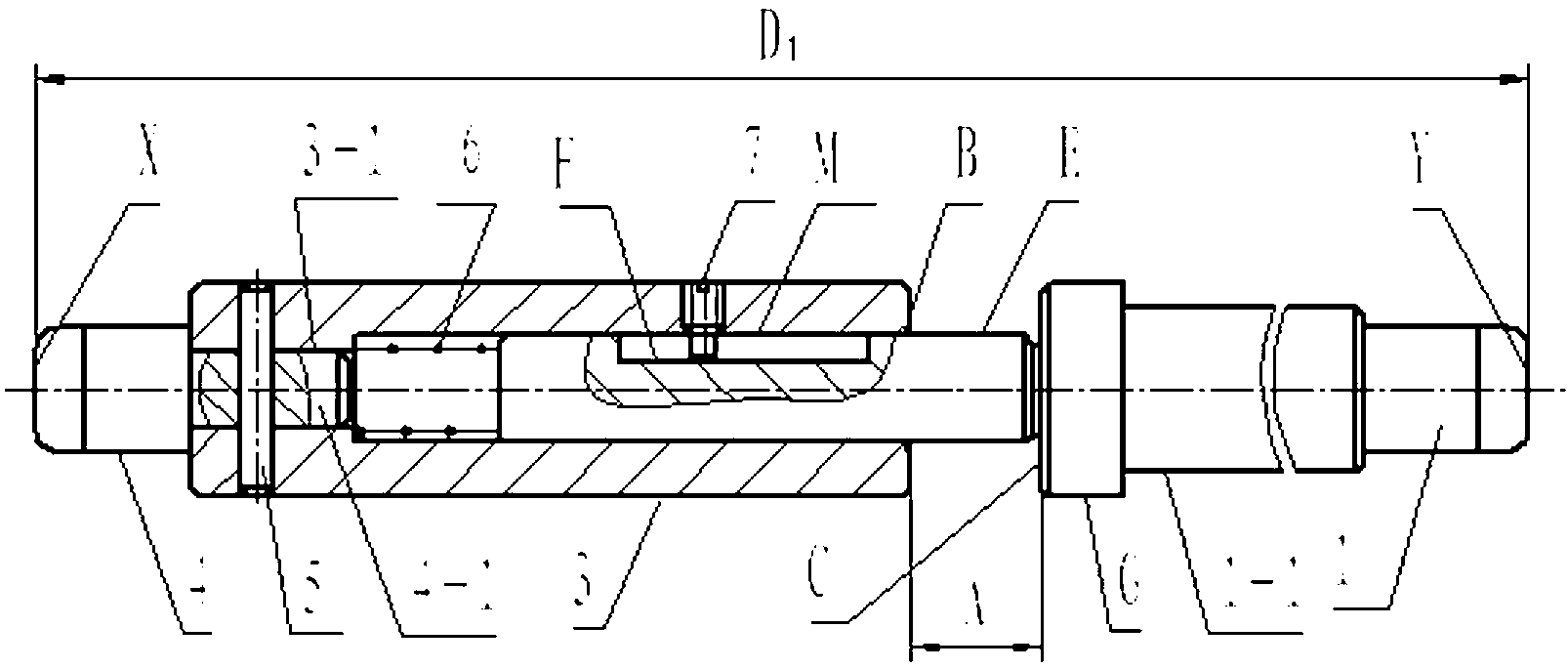
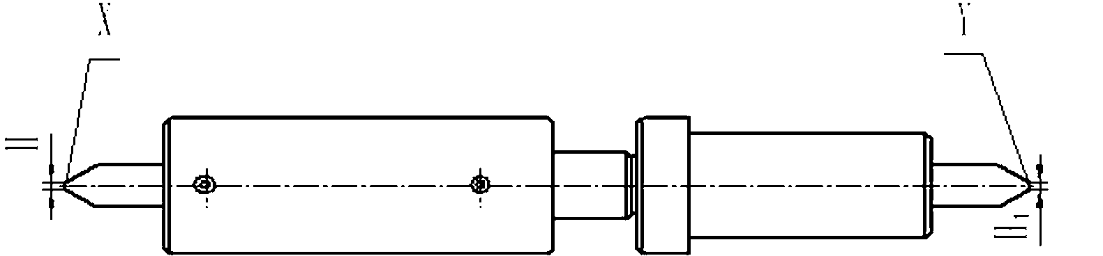
[0040] see figure 2 and image 3 As shown, the gauge for measuring the diameter of the track hole of a large-size steel wire bearing of the present invention includes a main body 1, a sleeve 3, a measuring head 4 and an elastic member 6 for moving the main body 1, and is characterized ...
PUM
 Abstract
Description
Claims
Application Information