Photovoltaic system suitable for high-voltage direct-current transmission

A photovoltaic system and high-voltage direct current technology, applied in the field of photovoltaic systems, can solve the problem of inability to transmit high-voltage direct current, and achieve the effect of improving the power of the inverter, stable power output, and small footprint

Inactive Publication Date: 2013-09-25
STATE GRID CORP OF CHINA +2
View PDF5 Cites 10 Cited by
  • Summary
  • Abstract
  • Description
  • Claims
  • Application Information

AI Technical Summary

Problems solved by technology

[0004] The purpose of the present invention is to provide a photovoltaic system suitable for high-voltage direct current transmission to solve the problem that the existing photovoltaic system is aimed at the use of alternating current grid and cannot be directly used for high-voltage direct current transmission

Method used


Image

  • Photovoltaic system suitable for high-voltage direct-current transmission
  • Photovoltaic system suitable for high-voltage direct-current transmission
  • Photovoltaic system suitable for high-voltage direct-current transmission

Examples


Embodiment Construction

[0020] The present invention will be described in further detail below in conjunction with the accompanying drawings.

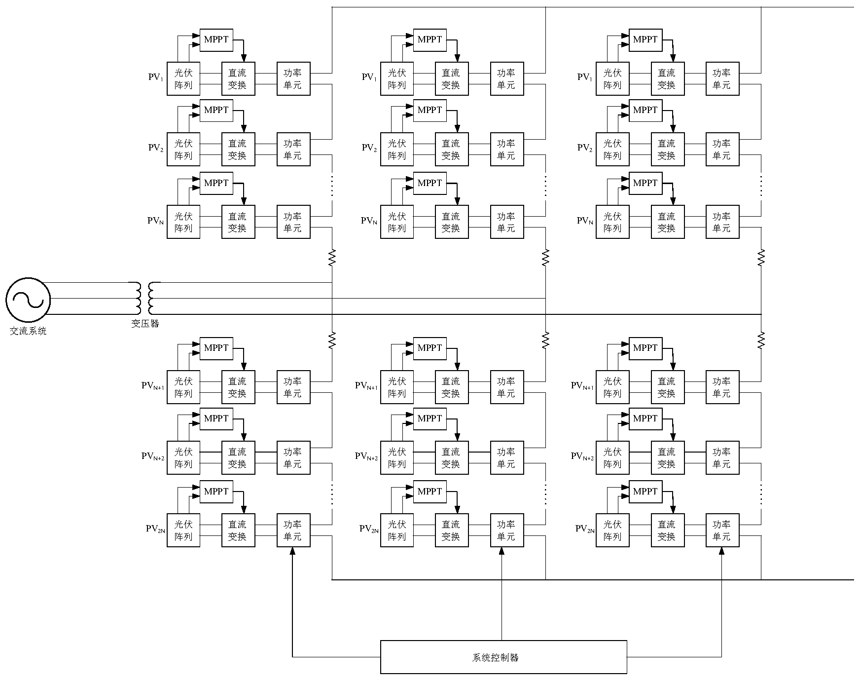
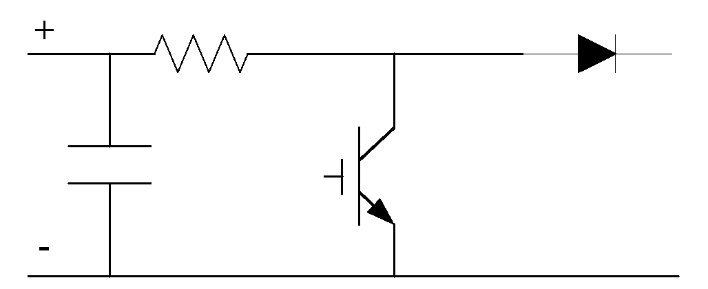
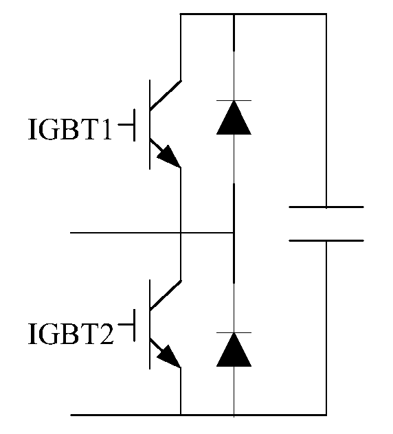
[0021] Such as figure 1 As shown, the photovoltaic system suitable for HVDC transmission includes a three-phase converter on the DC side for direct connection to the HVDC transmission line, and an auxiliary AC system on the AC side, and each phase is composed of two bridge arms connected in series. Each bridge arm includes at least one photovoltaic power generation device, and the output end of the photovoltaic power generation device is connected in series; the photovoltaic power generation device is composed of a photovoltaic array, a DC conversion circuit and a power unit whose output ends and input ends are sequentially connected, and the power unit is a switching circuit power unit , the output end of the power unit is the output end of the corresponding photovoltaic power generation device. Obviously, the number of photovoltaic power generation devices...


PUM


Abstract

The invention relates to a photovoltaic system suitable for high-voltage direct-current transmission. Electric energy produced by a photovoltaic array is output through a direct current converting circuit controlled by a tracking controller to serve as the energy source of a power unit, the system controller controls conduction and shutoff of switching elements in power units according to collected related data, the voltage stability of a capacitor is maintained, and a high-voltage and direct current formed by overlaying the voltage of various input power unit capacitors is obtained at the output end. A modularization power unit is adopted, the high-voltage direct current is output through the manner that the power units are mutually overlaid, long distance electricity transmission is carried out, redundancy control can be achieved, and system maintenance is convenient. A control strategy is simple and reliable, floor space is small, and transmission power is large.

Description

technical field [0001] The invention relates to a photovoltaic system suitable for high voltage direct current transmission. Background technique [0002] With the intensification of energy and environmental problems, the utilization of renewable resources such as solar energy has been paid more and more attention. It is predicted that by 2030, renewable energy will account for more than 30% of the total energy structure, and solar photovoltaic power generation will account for more than 10% of the world's total power supply; by 2040, renewable energy will Accounting for more than 50% of the total energy consumption, solar photovoltaic power generation will account for more than 20% of the total electricity; by the end of the 21st century, renewable energy will account for more than 80% of the energy structure, and solar power will account for more than 60%. These figures are enough to show the development prospects of the solar photovoltaic industry and its important strat...

Claims


Application Information

Patent Timeline
Patent Type & Authority Applications(China)
IPC IPC(8): H02N6/00H02J3/38
CPCY02E10/56
Inventor 张群王柏恒马仪成陈明赵倩
Owner STATE GRID CORP OF CHINA
Why Eureka
Try Eureka